Scanning exposure apparatus and method of manufacturing device

Inactive Publication Date: 2009-06-11
CANON KK
View PDF5 Cites 2 Cited by
  • Summary
  • Abstract
  • Description
  • Claims
  • Application Information

AI Technical Summary

Benefits of technology

[0010]It is an object of the present invention to provide a scanning exposure appa

Problems solved by technology

Therefore, it is an important issue to attain both an improvement in resolution and the assurance of the depth of focus necessa

Method used


Image

  • Scanning exposure apparatus and method of manufacturing device
  • Scanning exposure apparatus and method of manufacturing device
  • Scanning exposure apparatus and method of manufacturing device

Examples


Example

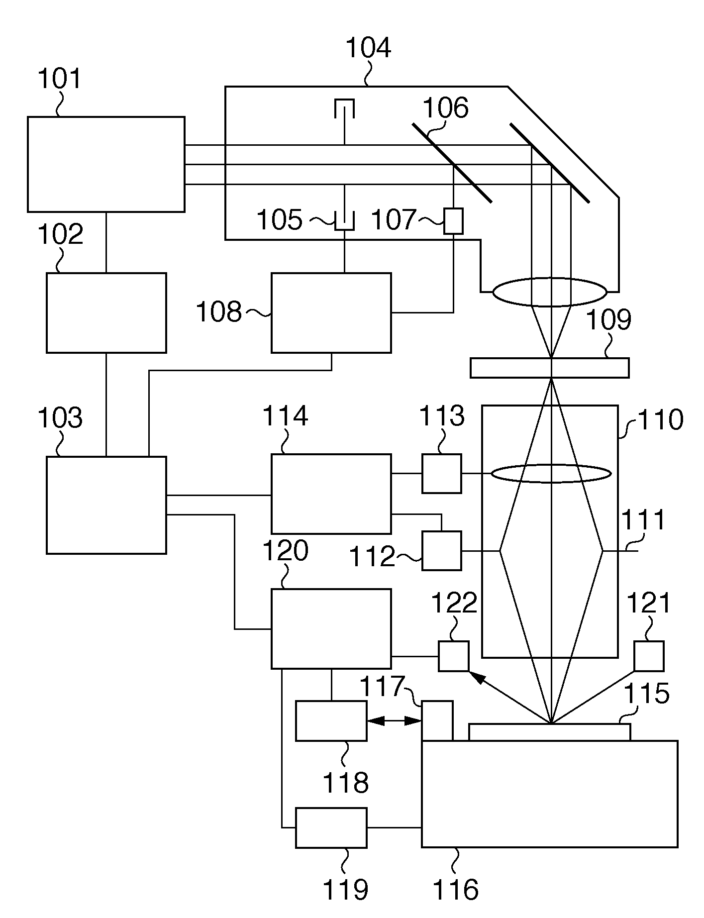
[0025]FIG. 1 shows the schematic arrangement of a scanning exposure apparatus according to an embodiment of the present invention. A light source 101 is, for example, an ArF or KrF excimer laser light source. The light source 101 performs pulsed oscillation of light with a far-ultraviolet wavelength of 193 nm or 248 nm. The light source 101 includes, for example, a front mirror which constitutes a resonator, a wavelength range narrowing module which includes, for example, a diffraction grating and prism, a monitor module, and a shutter. The diffraction grating narrows the exposure wavelength range. The monitor module includes, for example, a spectroscope and detector for monitoring the wavelength stability and spectral width. The central wavelength of exposure light emitted by the light source 101 can be changed. The light source 101 also includes an actuator with a high response characteristic, for changing the central wavelength of the exposure light in synchronism with the pulsed...


PUM


Abstract

A scanning exposure apparatus according to this invention has a light source which can change the central wavelength of exposure light to undergo pulsed oscillation, and scan-exposes a substrate with slit-like exposure light while periodically changing the central wavelength in synchronism with the pulsed oscillation of the exposure light. The scanning exposure apparatus includes a controller which controls the light source so that integrated values Sws and Swl obtained by integrating the intensity of the exposure light for each wavelength in the scanning direction in a short-wavelength range and long-wavelength range, respectively, assuming a target central wavelength as a reference satisfy:
|(Sws−Swl)/(Sws+Swl)|≦0.1

Description

BACKGROUND OF THE INVENTION[0001]1. Field of the Invention[0002]The present invention relates to a scanning exposure apparatus and a method of manufacturing a device.[0003]2. Description of the Related Art[0004]A reduction projection exposure apparatus has conventionally been employed in a process of manufacturing semiconductor devices such as an LSI and VLSI formed from ultrafine patterns. This apparatus reduces a circuit pattern drawn on a mask (reticle) and projects and prints it by exposure on a substrate (wafer) coated with a photosensitive agent, thereby forming a desired pattern on the substrate.[0005]Along with an improvement in the packaging density of semiconductor devices, further advance of micropatterning is required. This demand is increasing even for the exposure apparatus along with the development of the resist process.[0006]To improve the resolution of the exposure apparatus, there are a method of shortening the exposure wavelength and a method of increasing the nu...

Claims


Application Information

Patent Timeline
IPC IPC(8): G03B27/54G03B27/32
CPCG03F7/70575G03F7/70041
Inventor SUKEGAWA, TAKASHI
Owner CANON KK
Why Eureka
Try Eureka