Fan-turbine rotor assembly for a tip turbine engine

Active Publication Date: 2009-06-11
RAYTHEON TECH CORP
View PDF53 Cites 12 Cited by
  • Summary
  • Abstract
  • Description
  • Claims
  • Application Information

AI Technical Summary

Benefits of technology

[0010]The present invention therefore provides an assembly arrangement for a fan-turbine rotor a

Problems solved by technology

The axial flow relationship results in a relatively complicated elongated engine structure of considerable longitudinal length relative to the engine diameter.
This elongated shape may complic

Method used


Image

  • Fan-turbine rotor assembly for a tip turbine engine
  • Fan-turbine rotor assembly for a tip turbine engine
  • Fan-turbine rotor assembly for a tip turbine engine

Examples


Example

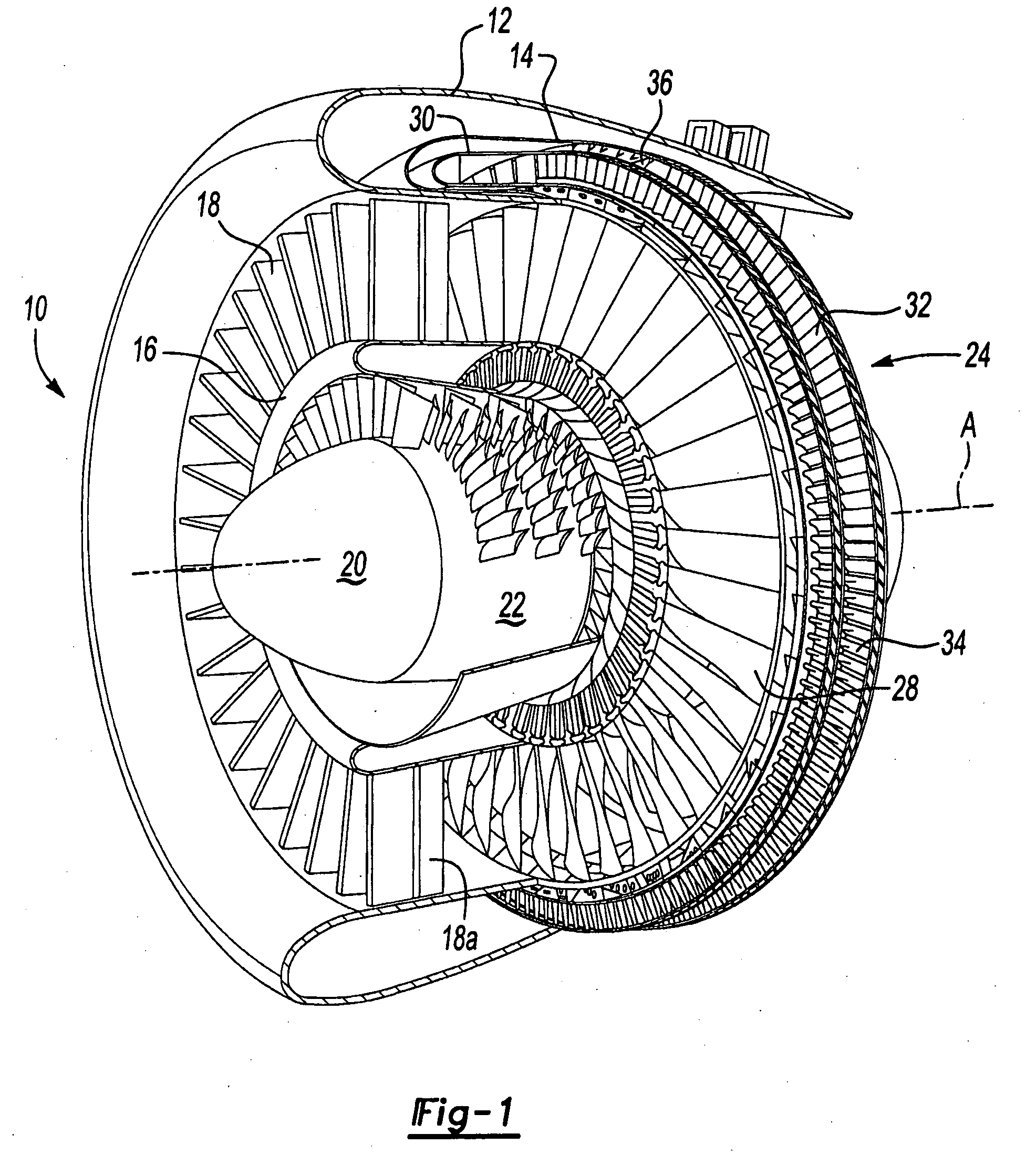
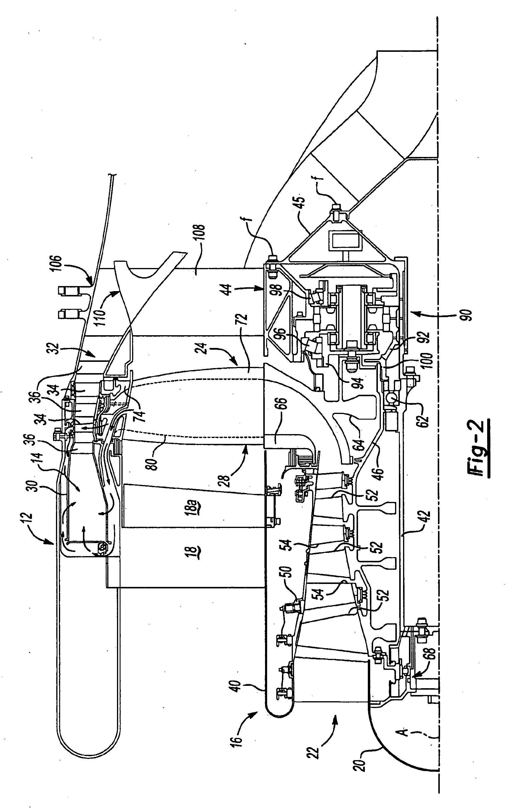
[0020]FIG. 1 illustrates a general perspective partial sectional view of a tip turbine engine type gas turbine engine 10. The engine 10 includes an outer nacelle 12, a nonrotatable static outer support structure 14 and a nonrotatable static inner support structure 16. A multitude of fan inlet guide vanes 18 are mounted between the static outer support structure 14 and the static inner support structure 16. Each inlet guide vane preferably includes a variable trailing edge 18A.

[0021]A nose cone 20 is preferably located along the engine centerline A to smoothly direct airflow into an axial compressor 22 adjacent thereto. The axial compressor 22 is mounted about the engine centerline A behind the nose cone 20.

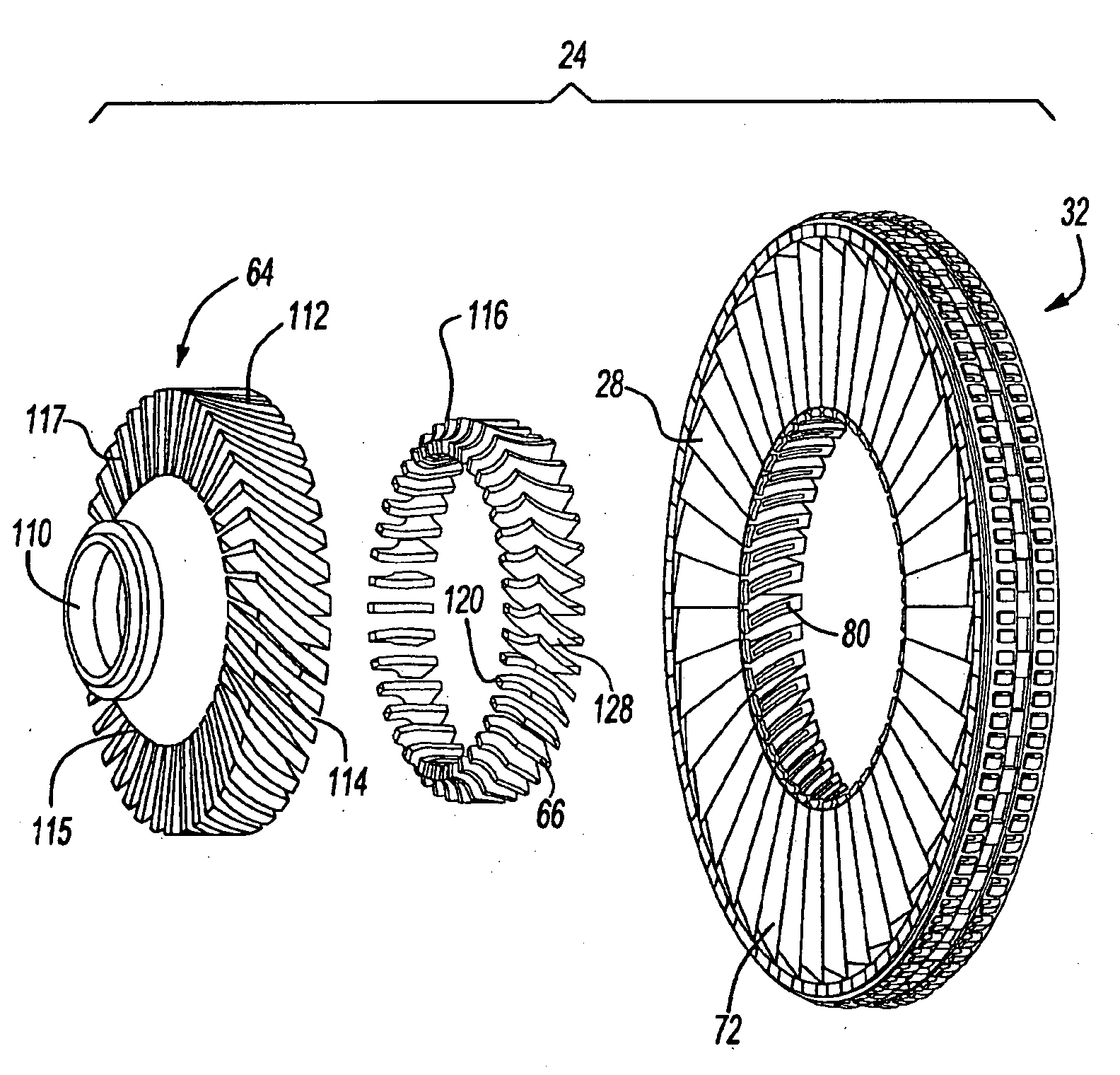
[0022]A fan-turbine rotor assembly 24 is mounted for rotation about the engine centerline A aft of the axial compressor 22. The fan-turbine rotor assembly 24 includes a multitude of hollow fan blades 28 to provide internal, centrifugal compression of the compressed airflow from th...


PUM


Abstract

A fan-turbine rotor assembly (24) for a tip turbine engine (10) includes a fan hub (64) with an outer periphery (112) scalloped by a multitude of elongated openings (114) which extend into a fan hub web (115). Each elongated opening defines an inducer receipt section (117) to receive an inducer section (66) and a hollow fan blade section (72). An inducer exhaust from each inducer section is located adjacent a core airflow passage (80) within each fan blade section to provide communication therebetween.

Description

BACKGROUND OF THE INVENTION[0001]The present invention relates to a tip turbine engine, and more particularly to a fan-turbine rotor assembly which provides mechanical retention between a multitude of rotational components.[0002]An aircraft gas turbine engine of the conventional turbofan type generally includes a forward bypass fan a compressor, a combustor, and an aft turbine all located along a common longitudinal axis. A compressor and a turbine of the engine are interconnected by a shaft. The compressor is rotatably driven to compress air entering the combustor to a relatively high pressure. This pressurized air is then mixed with fuel in a combustor and ignited to form a high energy gas stream. The gas stream flows axially aft to rotatably drive the turbine which rotatably drives the compressor through the shaft. The gas stream is also responsible for rotating the bypass fan. In some instances, there are multiple shafts or spools. In such instances, there is a separate turbine ...

Claims


Application Information

Patent Timeline
IPC IPC(8): F01D5/30F01D5/14B23P15/04
CPCF01D5/02F01D5/022F01D5/3007F02C3/073F02K3/068Y10T29/49321F04D29/54Y02T50/672F05D2240/55F05D2260/30F05D2300/603F04D25/045Y02T50/60
Inventor SUCIU, GABRIEL L.NORRIS, JAMES W.NORDEEN, CRAIG A.MERRY, BRIAN
Owner RAYTHEON TECH CORP
Why Eureka
Try Eureka