Non-contact pressure switch assembly

a non-contact, switch technology, applied in the direction of fluid pressure measurement, pulse technique, instruments, etc., can solve the problems of structure susceptible to contamination, corrosion, wear and tear

Inactive Publication Date: 2009-06-18
DELPHI TECH INC
View PDF8 Cites 14 Cited by
  • Summary
  • Abstract
  • Description
  • Claims
  • Application Information

AI Technical Summary

Benefits of technology

[0005]A pressure switch assembly includes a sensor body juxtaposable with a fluid chamber and a piston disposed in the sensor body for reciprocal movement therein. A deflectable diaphragm is interposed between the piston and fluid chamber, with a spring urging the piston against the diaphragm. A magnet is coupled to the piston, and a Hall effect sensor defining a field threshold line outputs a signal tha

Problems solved by technology

As understood herein, contacting technology, in which case hydraulic pressure deflects or moves a diaphragm or spring loaded piston to create a short circuit conditi

Method used


Image

  • Non-contact pressure switch assembly
  • Non-contact pressure switch assembly

Examples


Embodiment Construction

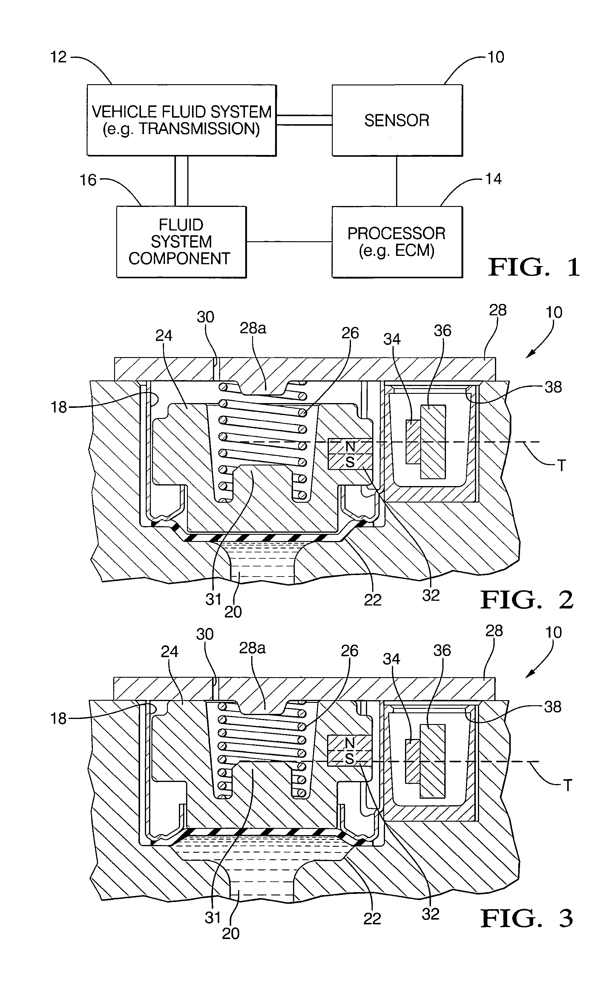
[0013]The present invention overcomes the drawbacks associated with contacting switches by using a non-contacting magnetic switch. As contemplated herein, the present switch may be used but is not limited to an automotive transmission.

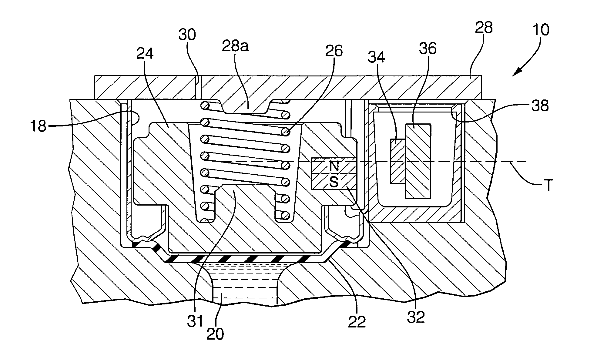
[0014]FIG. 1 illustrates a pressure sensor assembly 10 that is in fluid communication with a fluid system 12, such as a vehicle transmission system, to generate a signal representative of pressure in the fluid system 12. The signal may be sent (via appropriate processing circuitry and wired or wireless communication links) to a processor 14 such as a vehicle engine control module (ECM), with the processor 14 in response sending commands to a fluid system component 16 such as a valve or the like that is part of the fluid system 12.

[0015]FIG. 2 shows that the sensor 10 includes a hollow metal or hard plastic sensor body 18 juxtaposable with a fluid chamber 20, the pressure in which is imposed by the fluid system 12. A deflectable diaphragm 22 is engaged ...


PUM


Abstract

A non-contact pressure switch assembly for sensing pressure in, e.g., a vehicle. A piston with integrated magnet in a sensor body is moved under fluid pressure to change a magnetic field in which a Hall sensor is disposed inside the sensor body. The field changes polarity at the Hall sensor at a predetermined piston position.

Description

I. FIELD OF THE INVENTION[0001]The present invention relates generally to pressure switches, and more particularly to non-contact pressure switches for vehicles.II. BACKGROUND OF THE INVENTION[0002]Pressure switch manifolds are used in automotive transmission applications for direct sensing of fluid pressure. Applications include hydraulic feedback gear selection, shift timing / feel control, torque converter clutch control, solenoid feedback control, solenoid fault detection, and improved idle control.[0003]As understood herein, contacting technology, in which case hydraulic pressure deflects or moves a diaphragm or spring loaded piston to create a short circuit condition that closes the contacting switch at a predefined hydraulic pressure valve, can be used but these structures are susceptible to contamination, corrosion, and wear. Furthermore, conductive particle contamination can generate the close (short switch) condition without pressure actuation, and corrosion and wear can pre...

Claims


Application Information

Patent Timeline
IPC IPC(8): G01L7/08H01H35/34H01H36/00G01L9/14
CPCH01H35/34H03K17/97H01H36/0006
Inventor RECIO, MARIO A.LOZANO, JUAN C.
Owner DELPHI TECH INC
Why Eureka
Try Eureka