Supercharge Your Innovation With Domain-Expert AI Agents!

Imaging Apparatus

a technology of imaging apparatus and focusing aid, which is applied in the field of imaging apparatus, can solve the problems of hardly confirming in-focus and exposure state, hardly discernible details of subjects to be desired for practically photographing, and small number of pixels, so as to improve the convenience of us

Active Publication Date: 2009-06-18
MAXELL HLDG LTD
View PDF27 Cites 91 Cited by
  • Summary
  • Abstract
  • Description
  • Claims
  • Application Information

AI Technical Summary

Benefits of technology

[0005]In the aforementioned JP-A-11-341331, by enlarging a moving picture of a subject at a predetermined magnification and displaying it on the liquid crystal monitor during manual focusing, the user can be allowed to operate manual focus while watching details of the subject. But when, even in the course of manual focusing, the zoom magnification, for example, is desired to be changed, visibility of the entire angle of field is more convenient for operation than watching details of a subject, demonstrating that an image display complying with the contents of operation by the user can promote easy-to-operate capability.
[0007]To eliminate the disadvantages encountered in the background art, the present invention has its object to improve the user's convenience in handling an imaging apparatus and especially, to improve the convenience for the user to use various functions while watching the display monitor.

Problems solved by technology

But, as the number of pixels of an image-pickup device increases progressively in compliance with, for example, high definition (High Vision), the number of pixels becomes small with the pixel pitch rendered decreased in a small-size liquid crystal display, giving rise to a problem that details of a subject to be desired for practically photographing is hardly discernible and exact in-focus and exposure states can hardly be confirmed, making it difficult to make adjustments manually.

Method used


Image

  • Imaging Apparatus
  • Imaging Apparatus
  • Imaging Apparatus

Examples


embodiment 1

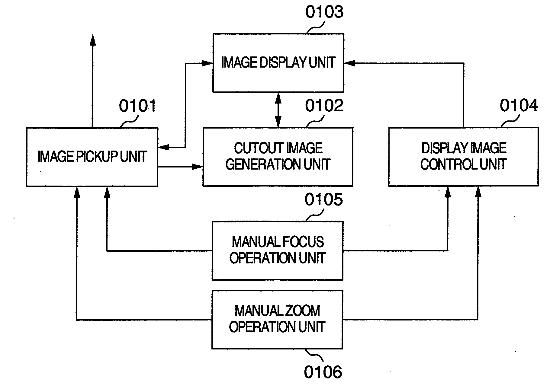
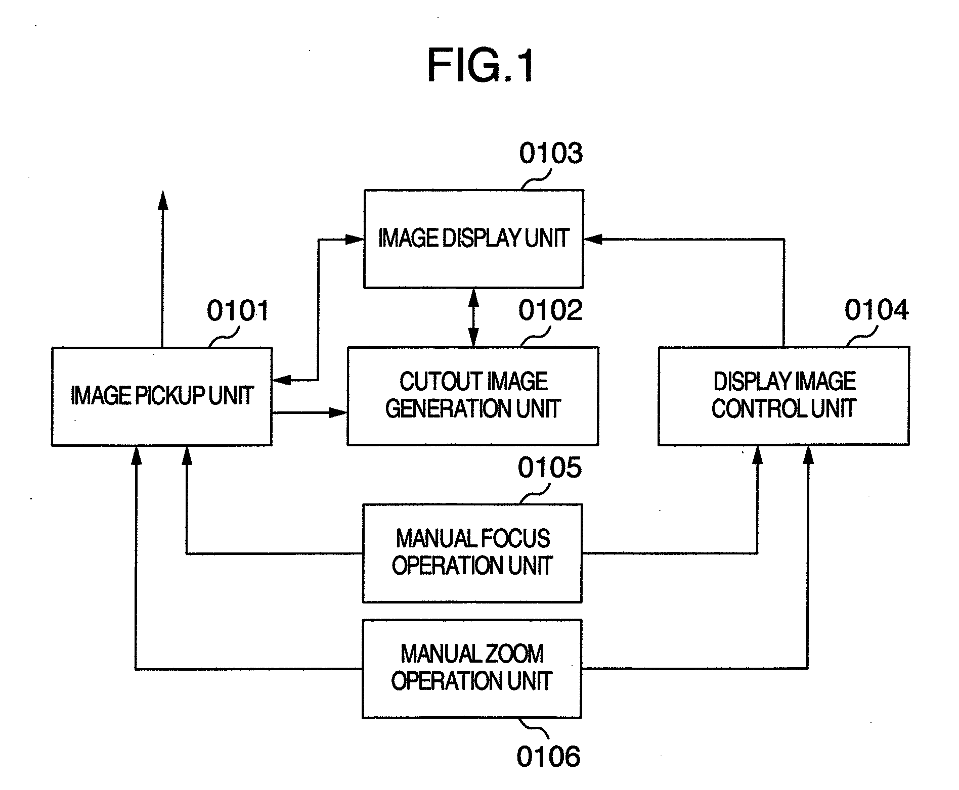
[0023]Referring first to FIG. 1, there is illustrated a first schematic diagram showing an imaging apparatus according to a first embodiment of the present invention. The imaging apparatus shown in FIG. 1 comprises an image pickup unit 0101, a cutout image generation unit 0102, an image display unit 0103, a display image control unit 0104, a manual focus operation unit 0105 and a manual zoom operation unit 0106.

[0024]In the imaging apparatus as shown in FIG. 1, the image pickup unit 0101, in which zoom and focus are variable, includes a group of lenses representing a zoom lens and a focus lens, a shutter, an image-pickup device such as CCD or CMOS, an AGC, an AD, a camera signal processing DSP, a moving picture processing LSI and a timing generator and operates to perform image pickup based on photoelectric conversion and deliver image or video data and image or video data for display which is reduced in accordance with the resolution of a display area of the image display unit 0103...

embodiment 2

[0038]Referring to FIG. 8, an imaging apparatus according to a second embodiment of the present invention is illustrated schematically. In FIG. 8, the imaging apparatus comprises an image pickup unit 0101, a cutout image generation unit 0102, an image display unit 0103, a display image control unit 0104 and a subject recognition unit 0811.

[0039]In the imaging apparatus as shown in FIG. 8, the image pickup unit 0101, in which zoom and focus are variable, includes a group of lenses representing a zoom lens and a focus lens, a shutter, an image-pickup device such as CCD or CMOS, an AGC, an AD, a camera signal processing DSP, a moving picture processing LSI and a timing generator and operates to perform image pickup based on photoelectric conversion and deliver image data and image data for display which is reduced in accordance with the resolution of a display area of the image display unit 0103. The image data for display may be generated by thinning the original image data at interva...

embodiment 3

[0043]Referring to FIG. 11, an imaging apparatus according to a third embodiment of the present invention is illustrated schematically. In FIG. 11, the imaging apparatus comprises a first image pickup unit 1101_1, a second image pickup unit 1101_2, a cutout image generation unit 0102, an image display unit 0103, a display image control unit 0104 and a stereo-image processing unit 1111.

[0044]In the imaging apparatus as shown in FIG. 11, each of the first and second image pickup units 1101_1 and 1101_2 in which zoom and focus are variable, includes a group of lenses representing a zoom lens and a focus lens, a shutter, an image-pickup device such as CCD or CMOS, an AGC, an AD, a camera signal processing DSP, a moving picture processing LSI and a timing generator and operates to perform image pickup based on photoelectric conversion and deliver image data. The stereo-image processing unit 1111 conducts a stereo-image process by using image data delivered out of each of the first and se...


PUM


Abstract

An imaging apparatus comprises an image pickup unit, a cutout image generation unit for cutting out a specified area in a pickup image taken by the image pickup unit to generate a cutout image enlarged at a specified magnification, an image display unit for displaying one or both of the pickup image taken by the image pickup unit and the cutout image generated by the cutout image generation unit, a display image control unit for controlling a method of displaying an image the image display unit displays, a manual focus operation unit for the user to control through manual operation the focus position of the image pickup unit, and a manual zoom operation unit for the user to control the zoom magnification of the image pickup unit.

Description

INCORPORATION BY REFERENCE[0001]The present application claims priority from Japanese application JP 2007-321486 filed on Dec. 13, 2007, the content of which is hereby incorporated by reference into this application.BACKGROUND OF THE INVENTION[0002]The present invention relates to an imaging apparatus with an image pickup unit and an image display unit.[0003]As a background art in the present technical field, one may refer to JP-A-11-341331, for example. The Patent Document aims at “providing an electronic imaging apparatus capable of performing manual focus control speedily and steadily with simplified construction” and discloses a solving technique reading “in an electronic imaging apparatus capable of switching between manual focus (including PF) and auto-focus, a system focus controller 80 controls an electronic zoom circuit 61 during manual focus so that a moving picture of a subject enlarged at a predetermined magnification higher than that during auto-focus may be displayed o...

Claims


Application Information

Patent Timeline
IPC IPC(8): H04N13/02H04N5/262H04N5/222H04N13/239
CPCH04N5/23212H04N5/23293H04N13/0296H04N13/0003H04N13/0239H04N5/23296H04N13/10H04N13/296H04N13/239H04N23/675H04N23/633H04N23/69G03B13/32H04N5/2628H04N5/272
Inventor HIROOKA, SHINICHIROCHIBA, HIROSHI
Owner MAXELL HLDG LTD
Features
  • R&D
  • Intellectual Property
  • Life Sciences
  • Materials
  • Tech Scout
  • Unparalleled Data Quality
  • Higher Quality Content
  • 60% Fewer Hallucinations
Learn More