Imaging lens unit and camera module

a technology of imaging lens and camera module, which is applied in the field of imaging lens unit and camera module, can solve the problems of increasing the optical path length, difficult to capture high-quality images, and difficult to reduce the size of imaging equipment, so as to achieve high-quality images, reduce optical path length, and reduce optical path length

Inactive Publication Date: 2009-06-18
HITACHT MAXELL LTD
View PDF2 Cites 6 Cited by
  • Summary
  • Abstract
  • Description
  • Claims
  • Application Information

AI Technical Summary

Benefits of technology

[0010]In the embodiment of the present invention, the surface shape on the image side of the second lens is formed in such a way that the maximum value of the angle between the tangent to the surface on the image side of the second lens and the normal to the optical axis is in the range of 65° to 90° within the effective diameter of the second lens. Thus, an exit angle of a ray output from the second lens is small. Accordingly, a chief ray angle of a ray output from the second lens is also small. This allows an angle of a ray incident on an image sensor to be substantially perpendicular to the image sensor. Further, because the imaging lens unit is composed of two lenses, an optical path length is short. It is thereby possible to achieve both reduction of the optical path length and capture of a high-quality image.
[0013]This allows an exit pupil position to be located away from an image pickup surface. This thus enables a ray to be incident on the image sensor at a more perpendicular angle. It is thereby possible to obtain a suitable image.
[0015]This enables reduction of the optical path length and increase in a light height of a light ray incident on the image sensor. Further, this allows the first lens to have an appropriate thickness for formation.
[0019]It is thereby possible to achieve both reduction of an optical path length and capture of a high-quality image.
[0020]The present invention enables reduction of an optical path length and capture of a high-quality image.

Problems solved by technology

However, it has been difficult to capture a high-quality image with use of such an imaging lens unit.
The increase in back focus leads to an increase in optical path length.
Accordingly, it has been difficult to reduce the size of imaging equipment by shortening the optical path length and input a ray to the image sensor substantially perpendicularly to an image pickup surface at the same time.
However, because the back focus is short in the technique disclosed in Japanese Unexamined Patent Application Publication No. 2005-121685, an angle of incidence of a ray on an image pickup surface is larger than a right angle.
It thus fails to capture a high-quality image.

Method used


Image

  • Imaging lens unit and camera module
  • Imaging lens unit and camera module
  • Imaging lens unit and camera module

Examples


example 1

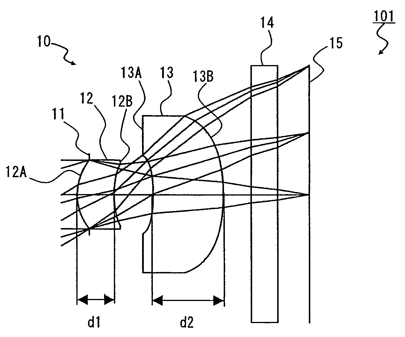
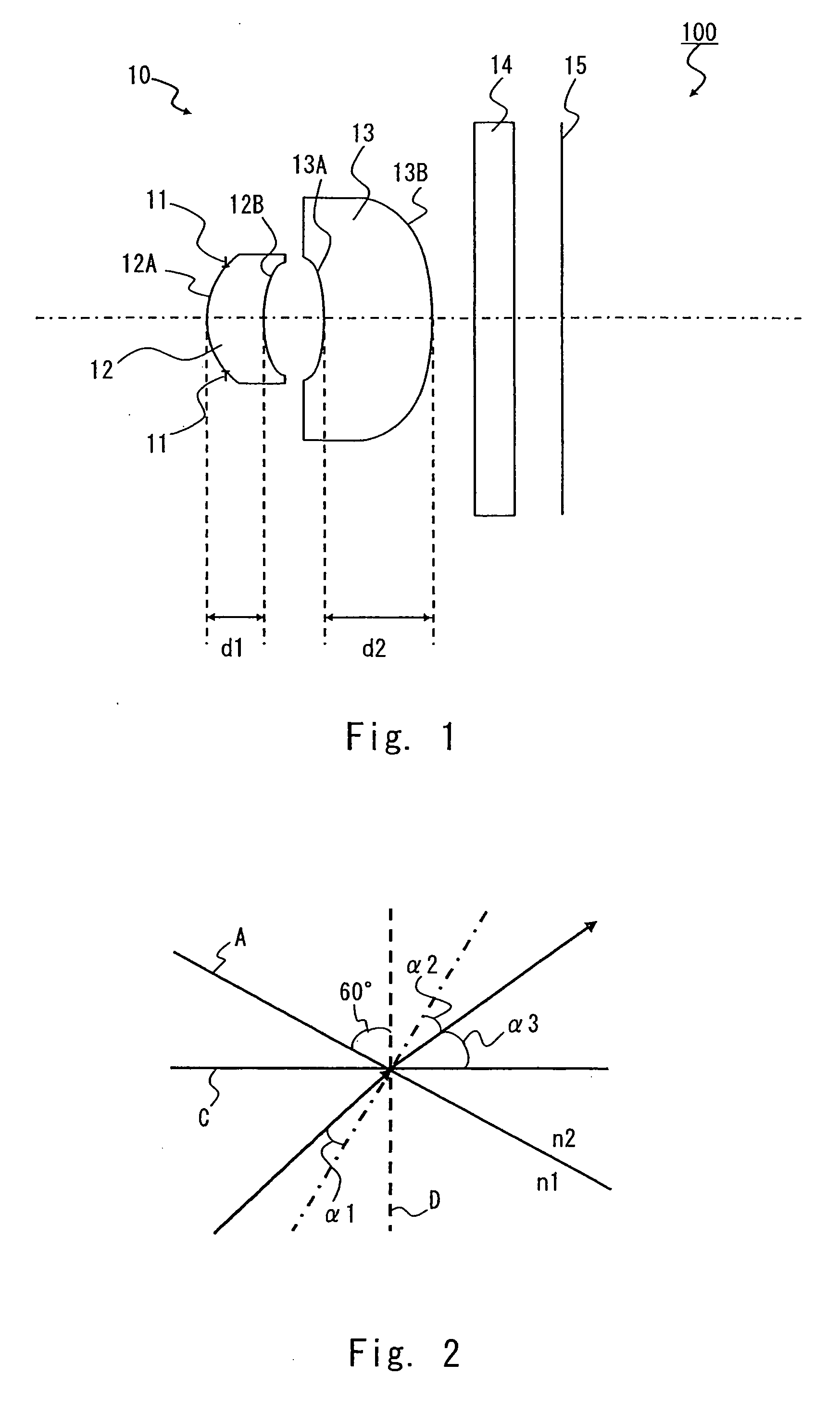
[0064]An example 1 of the present invention is described hereinafter. FIG. 5 is a schematic side view of a camera module 101 according to the example 1. In FIG. 5, from the object side, the aperture diaphragm 11 is referred to as a stop surface (ST), the object-side lens surface 12A of the first lens 12 is a second surface, the image-side lens surface 12B of the first lens 12 is a third surface, the object-side lens surface 13A of the second lens 13 is a fourth surface, the image-side lens surface 13B of the second lens 13 is a fifth surface, an object-side surface of the cover glass 14 is a sixth surface, an image-side surface of the cover glass 14 is a seventh surface, and an image pickup surface of the image sensor 15 is an eighth surface. Although a resin is used as a lens material of both the first lens 12 the second lens 13 in this example, a glass may be used instead.

[0065]The tables 1 and 2 show lens data according to the example 1.

[0066]The table 1 shows the curvature radiu...

example 2

[0074]An example 2 of the present invention is described hereinafter. FIG. 7 is a schematic side view of a camera module 102 according to the example 2. As shown in FIG. 7, the elements of the camera module 102 according to the example 2 are substantially identical to those of the camera module 101 according to the example 1 except for a first lens 22 and a second lens 23. The substantially identical elements are denoted by the same reference symbols and not described below. Although a resin is used as a lens material of both the first lens 22 the second lens 23 in this example, a glass may be used instead.

[0075]Like the example 1, in FIG. 7, from the object side, the aperture diaphragm 11 is referred to as a stop surface (ST), an object-side lens surface 22A of the first lens 22 is a second surface, an image-side lens surface 22B of the first lens 22 is a third surface, an object-side lens surface 23A of the second lens 23 is a fourth surface, an image-side lens surface 23B of the ...


PUM


Abstract

An imaging lens unit includes, from an object side, a diaphragm, a first lens, and a second lens placed on an image side of the first lens. The first lens is a positive meniscus lens convex toward the object side, and at least one side of the first lens has an aspherical surface. The second lens is a meniscus lens convex toward the image side, and at least one side of the second lens has an aspherical surface. Further, a maximum value of an angle between a tangent to a surface on the image side of the second lens and a normal to an optical axis is in a range of 65° to 90° within an effective diameter of the second lens.

Description

BACKGROUND OF THE INVENTION[0001]1. Field of the Invention[0002]The present invention relates to an imaging lens unit and a camera module and, particularly, to an imaging lens unit composed of two image pickup lenses and a camera module including the imaging lens unit.[0003]2. Description of Related Art[0004]An image sensor is becoming smaller in size today. With the size reduction of the image sensor, imaging equipment is also becoming smaller in size. In order to achieve the size reduction of a camera module, the development of an imaging lens unit composed of two image pickup lenses is desired. However, it has been difficult to capture a high-quality image with use of such an imaging lens unit.[0005]In order to capture a high-quality image, it is preferred that a ray is incident on an image sensor at a substantially perpendicular angle. In order for the ray to be incident on the image sensor substantially perpendicularly, it is generally necessary to increase back focus. The incr...

Claims


Application Information

Patent Timeline
Patent Type & Authority Applications(United States)
IPC IPC(8): G02B13/18
CPCG02B13/18G02B9/04G02B13/00
Inventor NAKANISHI, MASAKIMINAKAWA, YOSHIAKI
Owner HITACHT MAXELL LTD
Why Eureka
Try Eureka