Intelligent cooling fan device and fan rotation speed controlling method thereof

a technology of intelligent cooling fan and fan rotation speed, which is applied in the direction of machines/engines, mechanical equipment, engine starters, etc., can solve the problems of system crash, hardware device damage, affecting hardware device, etc., and achieve the effect of greatly simplifying the program architecture required by software and effectively improving the performance of the fan

Inactive Publication Date: 2009-06-18
INVENTEC CORP
View PDF18 Cites 20 Cited by
  • Summary
  • Abstract
  • Description
  • Claims
  • Application Information

AI Technical Summary

Benefits of technology

[0013]To sum up, the present invention can achieve the above function simply by using the interrupt event, and the interrupt service of BIOS or driver, and through looking up the table. Thus, not only the program architecture required by the software is greatly simplified, but also the performance of the fan is also effectively improved.

Problems solved by technology

If no cooling device is installed, the system crash may occur, or even the hardware devices may be damaged.
However, in actual usage, the extreme environments set by the manufacturer seldom encounters.
In this case, the fan rotating at a very high speed does no good to the CPU, but generates noise, which may adversely affect the hardware device and causes problems to the user.
Moreover, this design consumes much electric power, so the performance of the fan in cooling the CPU is rather poor.
However, as the BIOS controls the fan rotation speed through a segmented variable speed controlling mode, when the program is converted, the rising temperature of the CPU generates even more noise due to the higher acceleration of the fan.
Therefore, this design still has its own disadvantages.
Thus, circuit elements and software for performing the mathematical operations must be additionally installed, so the design cost and element cost are increased accordingly.
Moreover, the manner of adjusting the fan rotating speed through using the software program to detect the temperature in a polling mode through the BIOS has a rather poor performance, and consumes excessive large power.

Method used


Image

  • Intelligent cooling fan device and fan rotation speed controlling method thereof
  • Intelligent cooling fan device and fan rotation speed controlling method thereof
  • Intelligent cooling fan device and fan rotation speed controlling method thereof

Examples


Embodiment Construction

[0020]Reference will now be made in detail to the present preferred embodiments of the invention, examples of which are illustrated in the accompanying drawings. Wherever possible, the same reference numbers are used in the drawings and the description to refer to the same or like parts.

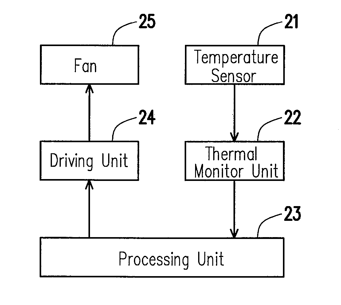
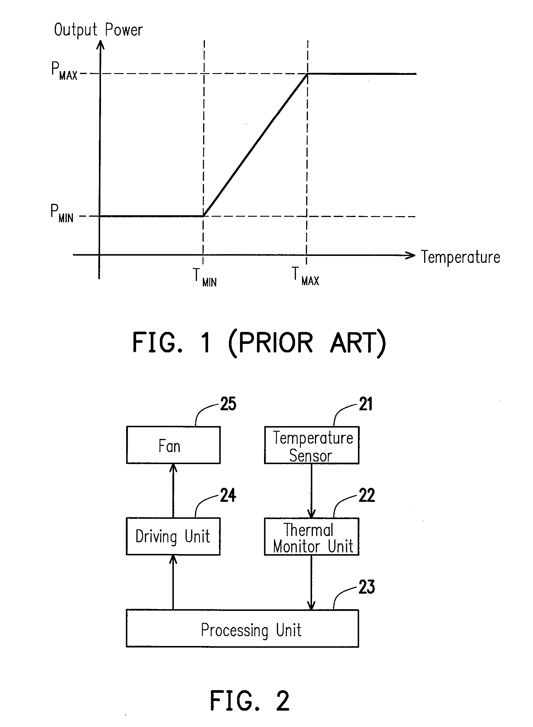
[0021]In the design of the current computer systems (e.g., personal computers, servers, and workstations), the thermo monitor function is considered as an important factor, in which the thermo monitor motion for the system and CPU plays an important role, and another important relevant function lies in the control of the fan rotation speed. The temperature of the CPU changes as the operating system is operated, so the rotation speed of the fan must be adjusted by the system. Embodiments of the present invention are described below, in which the intelligent cooling fan device and the method of controlling a fan rotation speed are used to maintain the system at a stable environment temperature.

[0022]FI...


PUM


Abstract

A fan cooling device and a method of controlling a fan rotation speed are provided. The fan cooling device includes a thermo sensor, a thermo monitor unit, a processing unit, a driving unit, and a fan. The thermo monitor unit compares the sensed result from the thermo sensor with at least one threshold, and decides whether or not to send an interrupt event according to the compared result. The processing unit executes an interrupt service according to the interrupt event, and then sets and outputs a value of the fan rotation speed. The driving unit drives the fan and controls the rotation speed of the fan according to the value of the fan rotation speed. The fan sends out a wind flow to reduce the internal temperature of a computer system or a CPU.

Description

CROSS-REFERENCE TO RELATED APPLICATION[0001]This application claims the priority benefit of Taiwan application serial no. 96147648, filed on Dec. 13, 2007. The entirety of the above-mentioned patent application is hereby incorporated by reference herein and made a part of this specification.BACKGROUND OF THE INVENTION[0002]1. Field of the Invention[0003]The present invention generally relates to a temperature control device and a method thereof, and more particularly, to a cooling fan device and a method of controlling a fan rotation speed.[0004]2. Description of Related Art[0005]With the rapid development of technology, computer hardware has been developed rapidly in recent years, for example, central processing units (CPUs) commonly used by hardware devices such as desktop computers, laptop computers, and even servers and workstations. The clock speed of the CPUs becomes increasingly high, so as to cater to the mass's requirements on processing an increasingly large amount of data...

Claims


Application Information

Patent Timeline
Patent Type & Authority Applications(United States)
IPC IPC(8): F01B25/00
CPCF01P7/04F01P2025/66F01P2025/08
Inventor CHANG, CHI-TSUNGLU, YING-CHIH
Owner INVENTEC CORP
Why Eureka
Try Eureka