Dynamic anterior vertebral plate

a technology of anterior vertebral plate and plate, which is applied in the field of dynamic anterior vertebral plate, can solve the problems of plates that do not secure the screw relative to the plate, are virtually gone from use, and are susceptible to having the screws back ou

Active Publication Date: 2009-06-18
K2M
View PDF7 Cites 47 Cited by
  • Summary
  • Abstract
  • Description
  • Claims
  • Application Information

AI Technical Summary

Benefits of technology

[0015]Also provided is a low profile dynamic anterior vertebral body plate that is secured to the underlying bone using a novel bone screw and locking element connection system that permits limited motion of the screw relative to the plate.
[0016]Also provided is a low profile dynamic anterior vertebral body plate, the plate being secured to the underlying bone by bone screws, each of the screws having a locking feature that prevents the screw from backing out from the plate while permitting limited motion of the screw relative to the plate.
[0017]Also provided is a low profile dynamic anterior vertebral body plate having a slidably engaged locking element configured to receive and secure a bone screw, the locking element facilitating

Problems solved by technology

These plates had no special provision for attaching the screws to the plate and as such were susceptible to having the screws back out of the plate over time.
There have been clinically reported instances of screws backing out of these type plates with resulting surgical complications.
Due to the lack of predictable security of the screw to the plate, plates which do not secure the screw relative to the plate have fallen out of favor and virtually disappeared from use.
While such mechanisms have worked to some degree, the addition of a small additional part, the set screw, at the time of surgery presents the potential hazard of dropping the set screw into the surgical field or otherwise misapplying the set screw to the screw head, for example, cross threading.
Further, these types of plates have not allowed for any limited motion of the plate relative to the screw so as to allow for the dynamics of a change in height of the vertebrae or for compression of the vertebrae.
These plates are very common and widely used; however, an inherent problem associated with such plates is the use of the additional very small retaining elements that can become disengaged from the plate and migrate into the surrounding soft tissues.
Further, difficulty experienced in accessing and disengaging the small locking elements and removing the screws from this type of plate

Method used


Image

  • Dynamic anterior vertebral plate
  • Dynamic anterior vertebral plate
  • Dynamic anterior vertebral plate

Examples


Embodiment Construction

[0035]Detailed embodiments of the present invention are disclosed herein; however, it is understood that the following description and each of the accompanying figures are provided as being exemplary of the invention, which may be embodied in various forms without departing from the scope of the claimed invention. Thus, the specific structural and functional details provided in the following description are non-limiting, but serve merely as a basis for the invention as defined by the claims provided herewith. The device described below can be modified as needed to conform to further development and improvement of materials without departing from the inventor's concept of the invention as claimed.

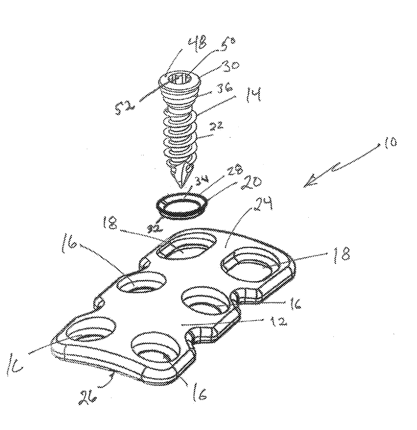
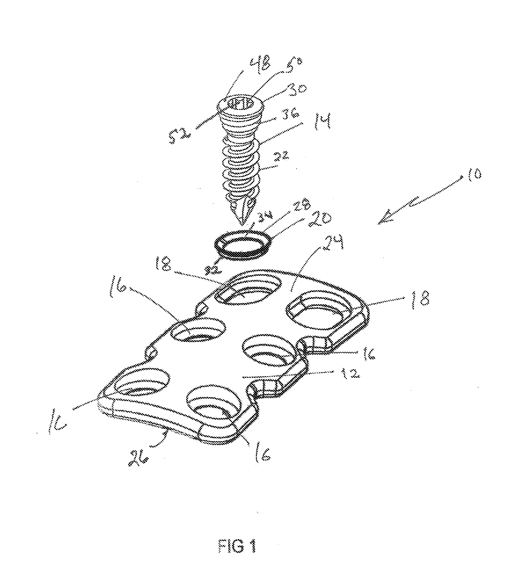
[0036]The dynamic anterior vertebral plate system, as generally shown at 10 in the accompanying figures, includes a low profile dynamic anterior vertebral body plate 12 that, when implanted in a patient, can be secured to the underlying bone using bone screws 14, such as those described in U...


PUM


Abstract

Provided is a novel system that includes a low profile dynamic anterior vertebral body plate and bone screws for the fixation and stabilization of the cervical spine, the system having a locking element through which the bone screw passes, the locking element being capable of movement relative to the plate when the bone screws are fully inserted and in a locked position. Also provided is a method of stabilizing cervical vertebrae using the disclosed system.

Description

BACKGROUND OF THE INVENTION [0001]1. Technical Field[0002]The present invention relates to devices and methods for use in orthopedic spine surgery. In particular, the present invention relates to a system that provides a low profile dynamic anterior vertebral body plate for the secure fixation and stabilization of the cervical spine without the need for additional small locking parts while permitting limited motion of the anterior plate.[0003]2. Background Art[0004]Disease, the effects of aging, or physical trauma resulting in damage to the spine has been treated in many instances by fixation or stabilization of the effected vertebra. The use of plates and screws for fixation and stabilization of the cervical vertebra has been widely accepted as a reliable practice and has proven to be highly successful clinically.[0005]The various plates, which are attached to the anterior vertebral bodies of the spinal column by bone screws have some common features such as relatively planar body ...

Claims


Application Information

Patent Timeline
IPC IPC(8): A61B17/70A61B17/58
CPCA61B17/8695A61B17/7059A61B17/8047
Inventor HARRIS, PETER M.WALLENSTEIN, TODD M.MCCLINTOCK, LARRY E.
Owner K2M
Why Eureka
Try Eureka