Sliding Fit, Pipe Arrangement And Exhaust Gas Treatment Device

Active Publication Date: 2009-06-25
PUREM GMBH
View PDF36 Cites 14 Cited by
  • Summary
  • Abstract
  • Description
  • Claims
  • Application Information

AI Technical Summary

Benefits of technology

[0007]Embodiments of the present invention are concerned with the problem of specifying an improved embodiment for a sliding fit or for a pipe arrangement or for an exhaust gas treatment device, w

Problems solved by technology

For example, this set of problems occurs in heating systems, cooling systems and exhaust systems.
This is unfavorable for applications which require a certain degree of gas-tightness since it is basically possible for gas to be exchanged through the sliding fit.
In addition,

Method used


Image

  • Sliding Fit, Pipe Arrangement And Exhaust Gas Treatment Device
  • Sliding Fit, Pipe Arrangement And Exhaust Gas Treatment Device
  • Sliding Fit, Pipe Arrangement And Exhaust Gas Treatment Device

Examples


Example

[0017]While the invention will be described in connection with certain preferred embodiments, there is no intent to limit it to those embodiments. On the contrary, the intent is to cover all alternatives, modifications and equivalents as included within the spirit and scope of the invention as defined by the appended claims.

DETAILED DESCRIPTION OF THE INVENTION

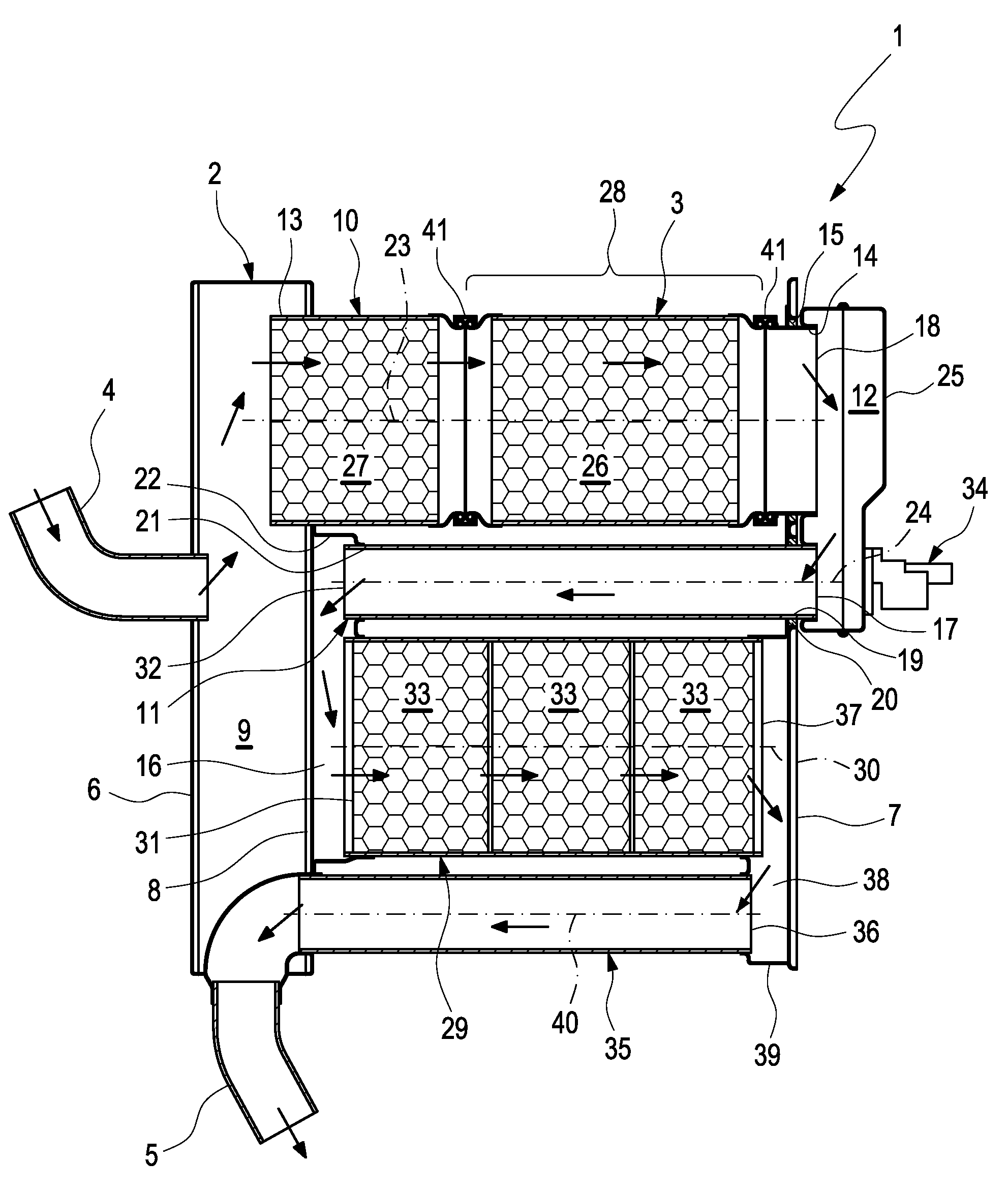
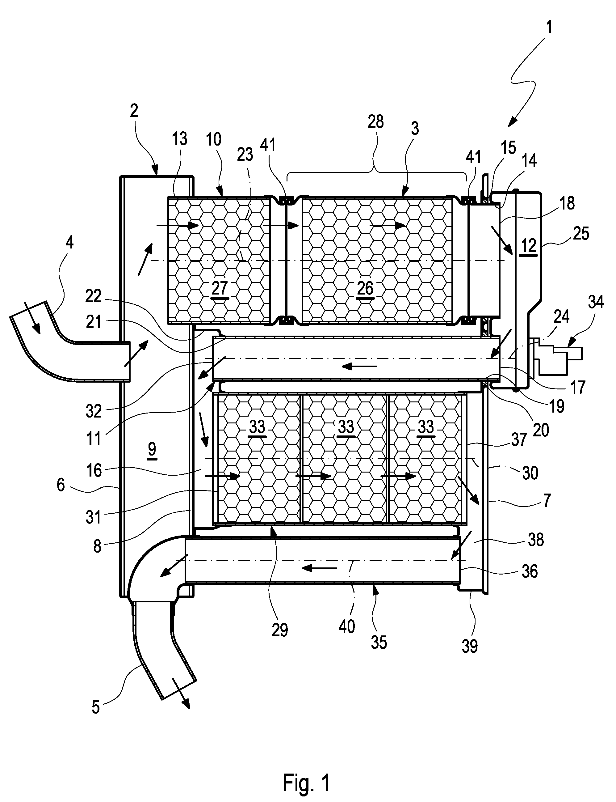
[0018]According to FIG. 1, an exhaust gas treatment device 1 comprises a housing 2 and at least one pipe arrangement 3. The housing 2 has at least one inlet 4 and at least one outlet 5. The housing 2 has, in the embodiment shown here, two end plates 6 and 7 and an intermediate plate 8. The first end plate 6 bounds an inlet chamber 9 with the intermediate plate 8 in the housing 2. The inlet 4 is connected, in the form of an inlet connector, to the first end plate 6.

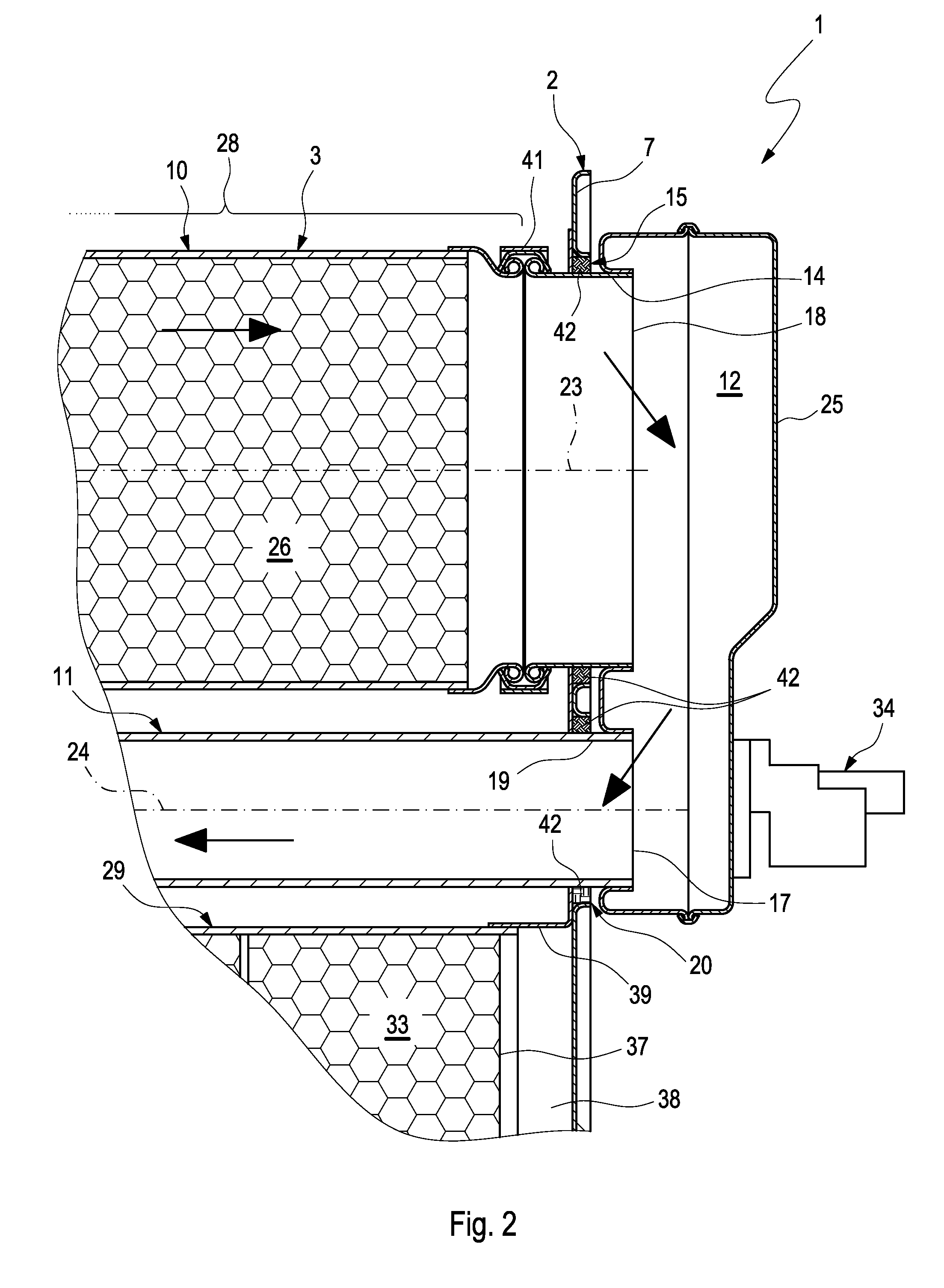
[0019]The pipe arrangement 3 comprises at least two pipes which communicate with one another, specifically a first pipe 10 and a second pipe 11. The first pipe 10 co...


PUM


Abstract

The present invention relates to a sliding fit for the axially movable bearing of a thermally loaded pipe on a component, in particular on an exhaust system of an internal combustion engine, having a wire mesh which is radially supported on the outside of the pipe and is secured directly or indirectly to the component.

Description

CROSS-REFERENCE TO RELATED PATENT APPLICATIONS[0001]This patent application claims the benefit of co-pending German Patent Application No. DE 102007062663.2, filed Dec. 24, 2007, the entire teachings and disclosure of which are incorporated herein by reference thereto.FIELD OF THE INVENTION[0002]The present invention relates to a sliding fit for the axially movable bearing of a thermally loaded pipe on a component, in particular on an exhaust system of an internal combustion engine. The invention also relates to a pipe arrangement in which at least one pipe is mounted with such a sliding fit on a carrier component. In addition, the present invention relates to an exhaust gas treatment device with such a pipe arrangement or with such a sliding fit.BACKGROUND OF THE INVENTION[0003]In order to be able to attach thermally loaded pipes permanently to a carrier, it is customary to fasten the respective pipe to a fixed bearing, on the one hand, and to a freely moving bearing, on the other ...

Claims


Application Information

Patent Timeline
IPC IPC(8): F16L27/12F01N3/021F01N3/10F01N13/08F01N13/18
CPCF01N3/035F01N3/2853F01N13/1811F01N13/0097F01N2310/04F01N2310/14F01N2450/30F01N13/1827
Inventor WIELAND, ARTHURKRAUSE, MICHAELLEHNEN, RAINERWIRTH, GEORG
Owner PUREM GMBH
Why Eureka
Try Eureka