Emission control system

Inactive Publication Date: 2009-06-25
MITSUBISHI MOTORS CORP +1
View PDF9 Cites 19 Cited by
  • Summary
  • Abstract
  • Description
  • Claims
  • Application Information

AI Technical Summary

Benefits of technology

[0022]A release portion where a contact with the injection flow of the additives which is deflected as a result of collision with the exh

Problems solved by technology

However, as it is required that a location where a catalyst is installed is secured in the vicinity of an exhaust side of an engine in order to meet the recent tendency of enhancing the exhaust emission purifying efficiency at the time of cold start, it becomes difficult to ensure such a sufficient fuel spray travel.
To make this happen, it becomes difficult to ensure a long enough fuel spray travel for mixture of fuel with exhaust gases between the fuel injection valve and the catalyst.
From the reasons regarding the installation of the fuel injection valve and the catalyst, the situation in which the fuel spray travel for mixture of fuel with exhaust gases becomes difficult to be ensured is seen not only the emission cont

Method used


Image

  • Emission control system
  • Emission control system
  • Emission control system

Examples


first embodiment

[0038]Hereinafter, the invention will be described based on a first embodiment shown in FIGS. 1 to 3.

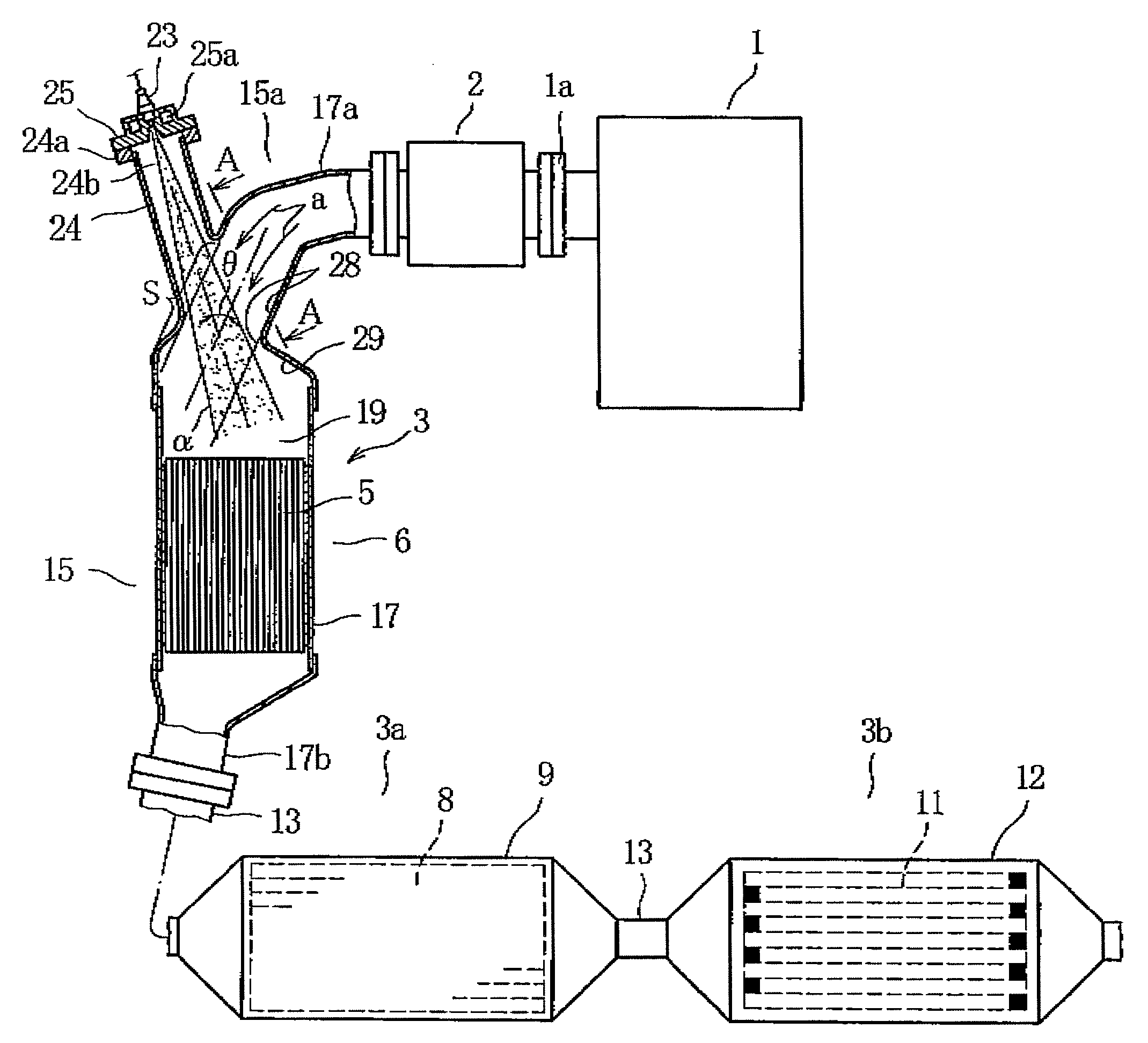
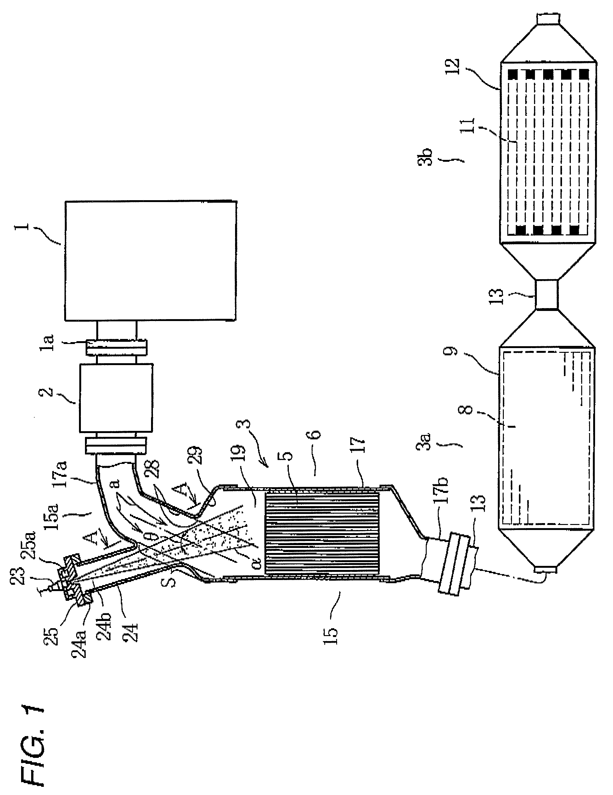
[0039]FIG. 1 shows an exhaust system of an internal combustion engine, for example, a diesel engine. In FIG. 1, reference numeral 1 denotes an engine main body of the diesel engine, 1a an exhaust manifold (only part of which is shown) of the engine main body 1 of the diesel engine, and 2 a supercharger or, in this embodiment, a turbocharger connected to an outlet of the exhaust manifold 1a.

[0040]An emission control system 3 is provided at an exhaust outlet of the turbocharger 2. A system in which a NOx removing system 3a for adsorbing NOx (oxides of nitrogen) contained in exhaust gases and periodically reduction removing the adsorbed NOx and a PM (particulate matter) capturing system 3b for capturing PM are combined together is used for the emission control system 3.

[0041]For example, used for the NOx removing system 3a is a configuration in which a catalytic converter 6, a catalyti...

second embodiment

[0064]In particular, in the second embodiment, for example, a curved recessed portion 30 is formed as a release portion on a wall surface of a downstream side exhaust pipe part T which intersects the flow of injected fuel α in such a manner that nothing in the exhaust pipe portion 15 is affected by the flow of injected fuel α when it is deflected. By this recessed portion 30, the contact of the flow of injected fuel α which is deflected with the wall portion of the exhaust pipe part T can be avoided, whereby a good mixture of the exhaust gases with the fuel can be promised. Moreover, since a wall portion of the recessed portion 30 causes exhaust gases which have come into contact with the recessed portion 30 to bounce back towards the flow of injected fuel α as is indicated by arrows b so as to cause the exhaust gases to collide with the fuel in the flow of injected fuel α, it can be expected that the mixture of the fuel with the exhaust gases is promoted further.

[0065]In addition, ...


PUM

PropertyMeasurementUnit
Thicknessaaaaaaaaaa
Angleaaaaaaaaaa
Flow rateaaaaaaaaaa

Abstract

An emission control system, includes: an exhaust pipe portion, adapted to guide exhaust gas from an engine to outside; a catalyst, accommodated in the exhaust pipe portion; an additive injection valve, provided at the exhaust pipe portion located at upstream side of the catalyst, and configured to inject additives to be supplied to the catalyst toward a flow of the exhaust gas in the exhaust pipe portion. The exhaust pipe portion has a flow path section located at upstream side of the catalyst, which intersects an injection flow of the additives injected by the additive injection valve, and the flow path section is made to have substantially the same shape as an injection region of the injection flow which confronts the exhaust gas.

Description

BACKGROUND OF THE INVENTION[0001]For purification of exhaust emissions from a car (a vehicle) having a diesel engine, an emission control system is used in which a adsorption type NOx catalyst, a selective reduction type NOx catalyst and a diesel particulate filter are combined together to prevent the emission of NOx (oxides of nitrogen) and PM (particulate matter) which are contained in exhaust emissions from a diesel engine to the atmosphere[0002]An emission control system like this adopts a construction in which a catalyst referred to as a pre-stage catalyst such as an oxidation catalyst, a NOx trap catalyst or a selective reduction type NOx catalyst is provided in an interior of an exhaust pipe portion which expels exhaust gases discharged from the engine to the outside thereof, and a fuel injection valve (such as one for adding a reducing agent) which injects a fuel required for reaction of the catalyst to an upstream side of the catalyst, for example, the oxidation catalyst.[0...

Claims


Application Information

Patent Timeline
IPC IPC(8): F01N3/18F01N13/08
CPCB01F3/04049F01N3/035F01N3/0807F01N3/0842F01N3/2033F01N13/009F01N3/36F01N13/08F01N2470/10Y02T10/26F01N3/2892Y02T10/12B01F23/2132B01F2025/931B01F25/314B01F25/4335F01N3/24B01D53/94F01N3/28
Inventor KOJIMA, MITSUTAKAKIMURA, HIROYUKIOKADA, KOJIROSHIGAHARA, KEIHATA, MICHIHIROKAWASHIMA, KAZUHITOKOGA, KAZUOMAEHARA, KAZUTOISHII, HAJIMA
Owner MITSUBISHI MOTORS CORP
Why Eureka
Try Eureka