
Engine Management

a technology for engine management and engine components, applied in the direction of electrical control, structural/machine measurement, instruments, etc., can solve the problems of ems technology remaining restricted to parameter based systems, known engine management systems suffering from various problems, and known systems requiring significant initial calibration

Inactive Publication Date: 2009-06-25
CORNWELL RICHARD CHARLES ELLIOT +6
View PDF15 Cites 20 Cited by
  • Summary
  • Abstract
  • Description
  • Claims
  • Application Information

AI Technical Summary

Benefits of technology

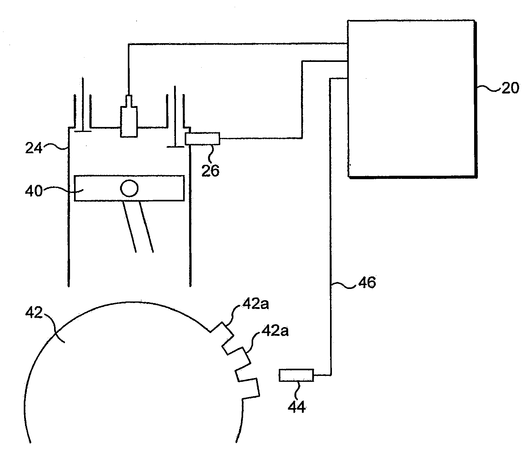
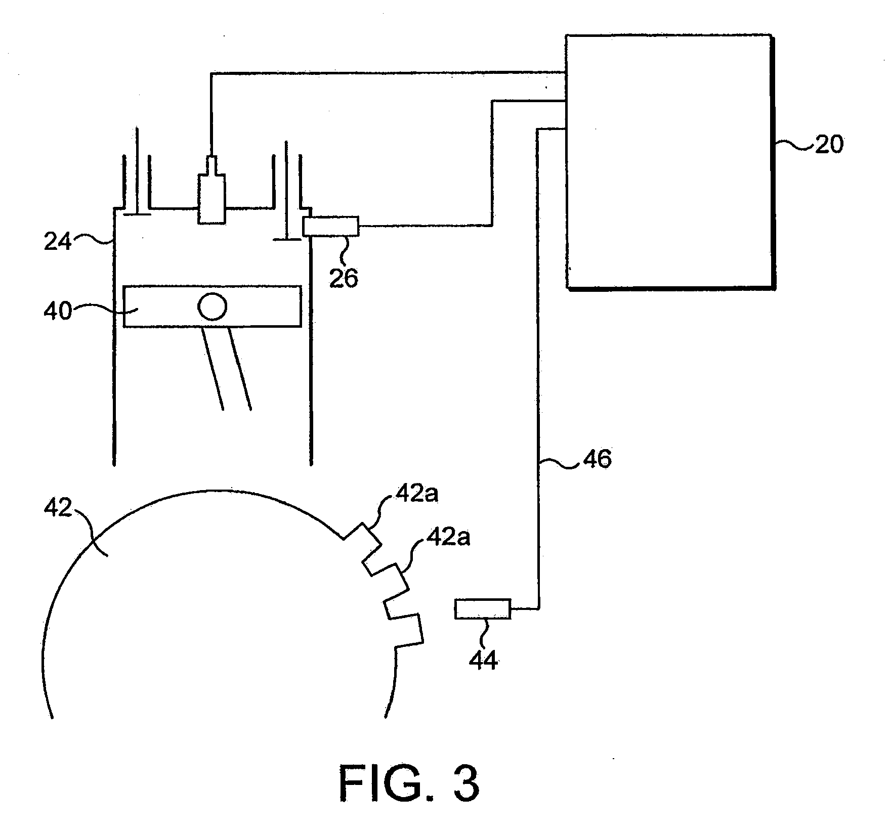
"The invention is a system and method for improving engine management by using real-time cylinder pressure data. The current systems are restricted to parameter-based systems that require calibration and have inaccuracies arising from the inferred data. The invention compensates for factors such as variations between engine builds and individual cylinders, as well as in-service wear. It also uses a single cylinder in cross section to demonstrate the pressure variation during a combustion cycle. The invention provides a more accurate and efficient engine management system."

Problems solved by technology

Known engine management systems suffer from various problems.
EMS technology remains restricted to parameter based systems.
As well as introducing a high data storage demand, therefore, known systems require significant initial calibration.
As a result the systems do not compensate for factors such as variations between engine builds let alone individual cylinders, and in-service wear.
Accordingly the look-up tables may be inaccurate ab initio for an individual engine, and will become less accurate still with time.
Generally much of the engine performance data is very indirect and is based on multiple inferences from sensors together with the mapped or modeled data which can give rise to inaccuracies arising from the inferences made or from differences between vehicles based on production tolerances or indeed differences between conditions in individual cylinders within an engine.
Furthermore such approaches do not compensate for changes in performance arising from in-service wear.
A problem with this is that the engine torque is in fact inferred from easily measurable variables such that airflow in a gasoline engine or fuel flow in a diesel engine.
Accordingly the value for torque that is derived is indirect and inaccurate, suffering from the disadvantages set out above.
Although torque sensors are known, these are costly and are not robust.
However in known systems these values are currently mapped or modeled at the engine manufacture stage and hence suffer from the problems set out above.

Method used


Image

  • Engine Management
  • Engine Management
  • Engine Management

Examples


Embodiment Construction

[0022]The following discussion of an embodiment of the invention relates to its implementation in relation to a four stroke combustion ignition engine comprising a diesel engine. However it will be appreciated that the invention can be applied equally to other stroke cycles and types of internal combustion engines including spark-ignition engines, with appropriate changes to the model parameters. Those changes will be apparent to the skilled person and only the best mode presently contemplated is described in detail below. Like reference numerals refer to like parts throughout the description.

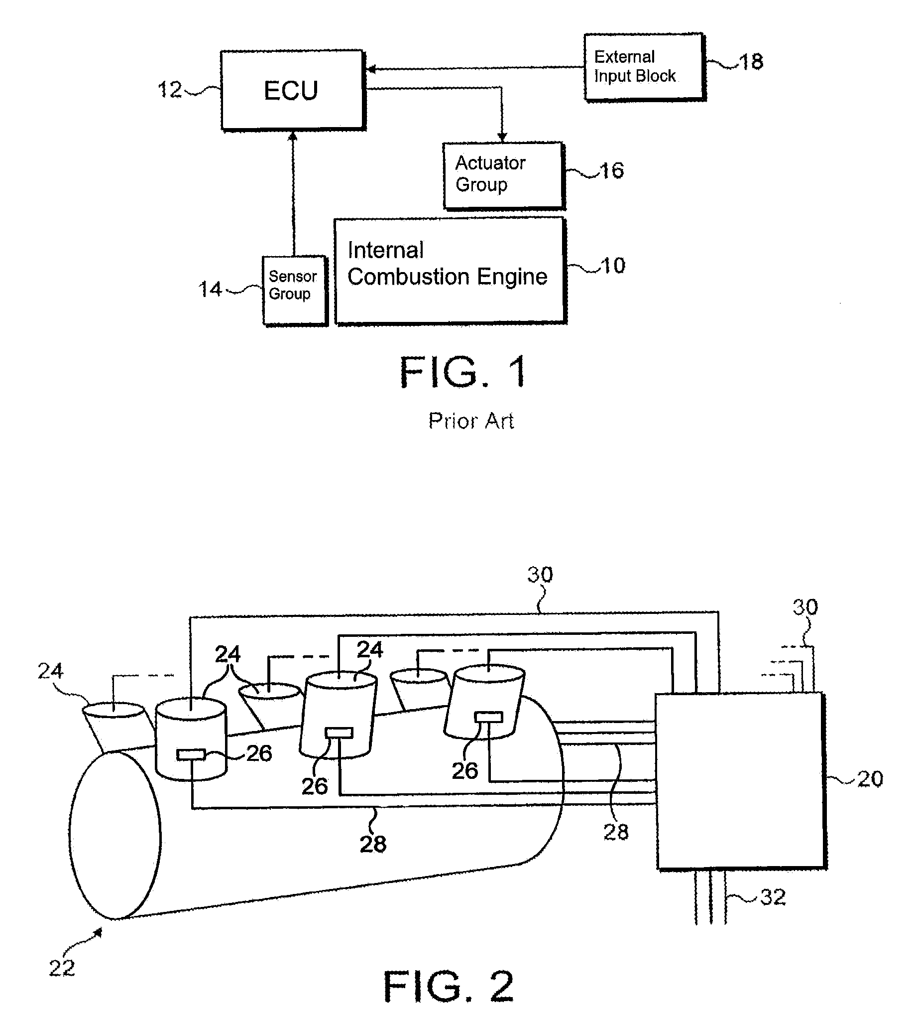
[0023]FIG. 2 is a schematic view showing the relevant parts of an engine management system according to the present invention in conjunction with a six cylinder engine. An engine control unit is designated generally 20 and controls an engine designated generally 22. The engine includes six cylinders designated generally 24. Each cylinder includes a pressure sensor 26 which connects to the ECU v...


PUM


Abstract

An in-cylinder pressure sensor obtains a high resolution pressure curve for each cylinder cycle allowing the various data to be derived for improved monitoring and control of operation of the engine. A more accurate measure of work done by the engine is obtained allowing more accurate estimation of the vehicle torque and hence real torque control. In addition, engine losses can be more accurately calculated and the estimates corrected yet further by obtaining an accurate top dead centre position for the engine cylinders.

Description

CROSS-REFERENCE TO RELATED APPLICATIONS[0001]This application is a divisional of application Ser. No. 10 / 536,619, filed Aug. 25, 2006, the entire disclosure of which is hereby incorporated by reference.BACKGROUND OF THE INVENTION[0002]The invention relates to a system and method providing improved engine management and in particular using real time cylinder pressure data. The aspects discussed herein are an extension of the concepts disclosed in International patent application no. PCT / GB02 / 02385 entitled “Improved Engine Management” commonly assigned herewith and incorporated herein by reference.[0003]Known engine management systems (EMS) monitor and control the running of an engine in order to meet certain pre-set or design criteria. Typically these are good drivability coupled with high fuel efficiency and low emissions. One such known system is shown schematically in FIG. 1. An internal combustion engine 10 is controlled by an engine control unit 12 which receives sensor signals...

Claims


Application Information

Patent Timeline
Patent Type & Authority Applications(United States)
IPC IPC(8): G01M15/00F02B1/12F02D35/02F02D41/14F02D41/34
CPCF02B1/12F02D35/023F02D41/009F02D41/2432F02D2200/1004F02D2200/1006F02D41/1497
Inventor CORNWELL, RICHARD CHARLES ELLIOTWINSLETT, EDWARD COLINNOBLE, ANDREW DAVIDCOOPER, BRIAN GORMANTRUSCOTT, ANTHONYGREENWOOD, DAVIDDILIETO, NICOLA
Owner CORNWELL RICHARD CHARLES ELLIOT
Learn More