Cordless window blind structure

a window blind and cordless technology, applied in the direction of door/window protective devices, construction, building components, etc., can solve the problems of inconvenient operation, blind body cannot be accurately positioned, hands touching the area, etc., and achieve the effect of reducing the requirement of cutting down

Inactive Publication Date: 2009-06-25
NIEN MADE ENTERPRISE CO LTD
View PDF11 Cites 25 Cited by
  • Summary
  • Abstract
  • Description
  • Claims
  • Application Information

AI Technical Summary

Benefits of technology

[0012]In accordance with the teachings of the present invention, applicants have developed a cordless window blind structure, which may achieve greater extent of cut-down requirement at both distant ends of the window blind.
[0013]The present invention is further direct to a cordless window blind structure, capable of increasing a full length for the window blind.
[0017]Furthermore, the moving stroke of the blind body of the present invention is determined according to the lateral movement of the movable seat therealong the head rail, and the pulley block and the cord-winding assembly are both constructed and arranged within the movable seat thereby, lateral moving space of the movable seat therealong the head rail is further increased, providing available spare space at both distant ends of the head rail for cut-down requirement, this may in turn increase the extent of maximum expansion characteristics on the blind body, which is equivalent to the full length of the window blind.
[0018]Furthermore, if both the head rail length and the blind body full length of the window blind of the present invention are the same as that of the prior art, by increasing the available space where the movable seat is moved within the head rail, both the distance between the first end of the head rail and the first positioning element and the distance between the second end of the head rail and the predetermined position (or the second positioning element) can substantially be increased as well, allowing the blind to have greater extent of cut-down portion on both distant ends of the head rail.
[0019]With the present invention, the blind assembly can not only provide greater extent of head rail cut-down needs but also lengthen the maximum expansion characteristics on the blind body, in other words, to increase the drop length of the window blind.

Problems solved by technology

However, the small frictional surface of the pull cord tends to rub against the hands exerting force thereon, and thus hurting the area of hands contacting with it.
Besides, in case of an excessive down-pulling force exerted onto the pull cord or a sudden release at a great speed, the blind body cannot be accurately positioned in a desirable position and the adjustment process must be repeated over again, which is quite inconvenient in operation and may hurt the user's hand.
The window has front and back panels installed at different rails, so that both the winding apparatus and counterbalance system must be installed in respective track, which complicates the whole structure and occupies quite a large space.
However, as the inter-engagement of the spring tension mechanism and the whole window curtain assembly does not generate a friction force during practical operation thereby, the whole curtain body must be completely drawn out and then fastened to a buckle through a handle means.
That is, the window blind is not capable of achieving a counterbalanced state at any particular position.
Also, the spring tension mechanism must be correspondingly fixed to two utmost ends of a tubular frame (the head rail), so the structure of such window curtain assembly is not capable for a stock size window blind which may require cut-down at both distant ends in accordance with the customers' needs.
However, the associated head rail components (for example, a fixing base and a cord-winding control unit) must be respectively fixed on both utmost ends of the head rail, limiting the possibility for head rail cut-down at both distant ends.
However, once the movable seat is lengthened, this in turn will substantially shorten the distance between the movable seat and the cord-winding control unit, and further minify the spare space available within the head rail, therefore, the blind may not be suitable for cut-down needs.
As described above, once the distance between the movable seat and the cord-winding control unit is shortened, this in turn may place limitations on the maximum stretch characteristics that the window blind can perform, in other words, the full length of the blind is restrained.
And the pulley block of the fixing base and the torsion spring assembly of the cord-winding control unit are respectively fixed at two utmost ends of the head rail thereby, the window blind is not suitable for cut-down performance.

Method used


Image

  • Cordless window blind structure
  • Cordless window blind structure
  • Cordless window blind structure

Examples


Embodiment Construction

[0030]Preferred embodiments of the present invention are described in detail below with reference to the accompanying drawings.

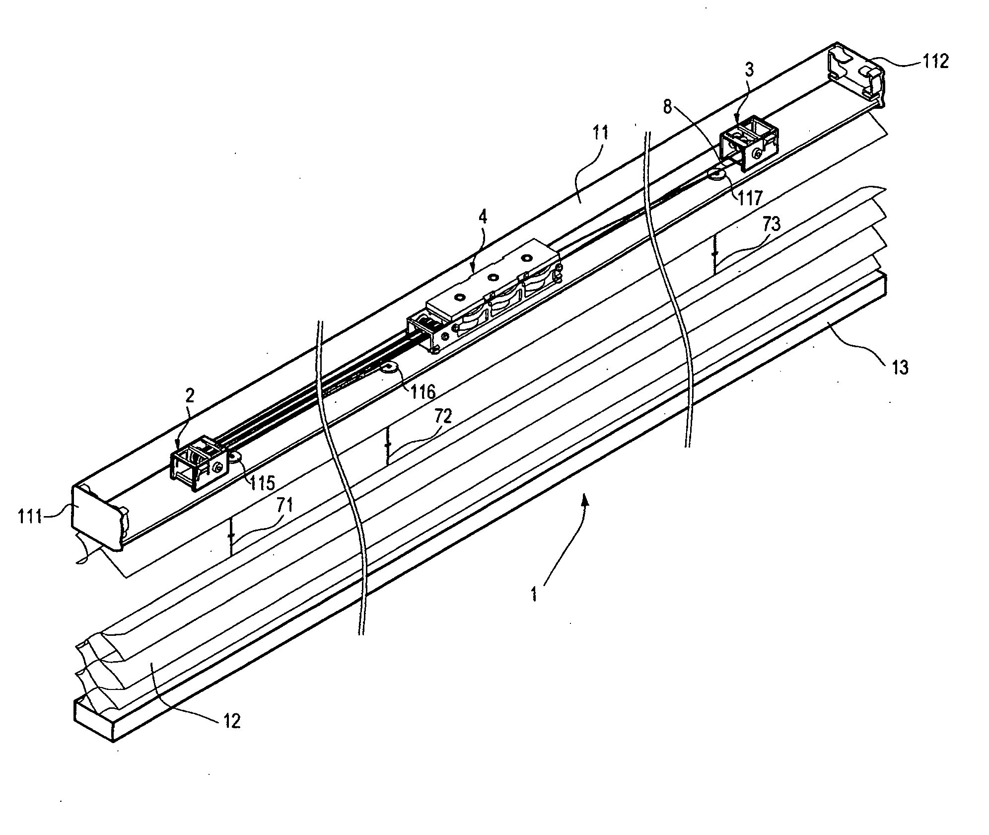
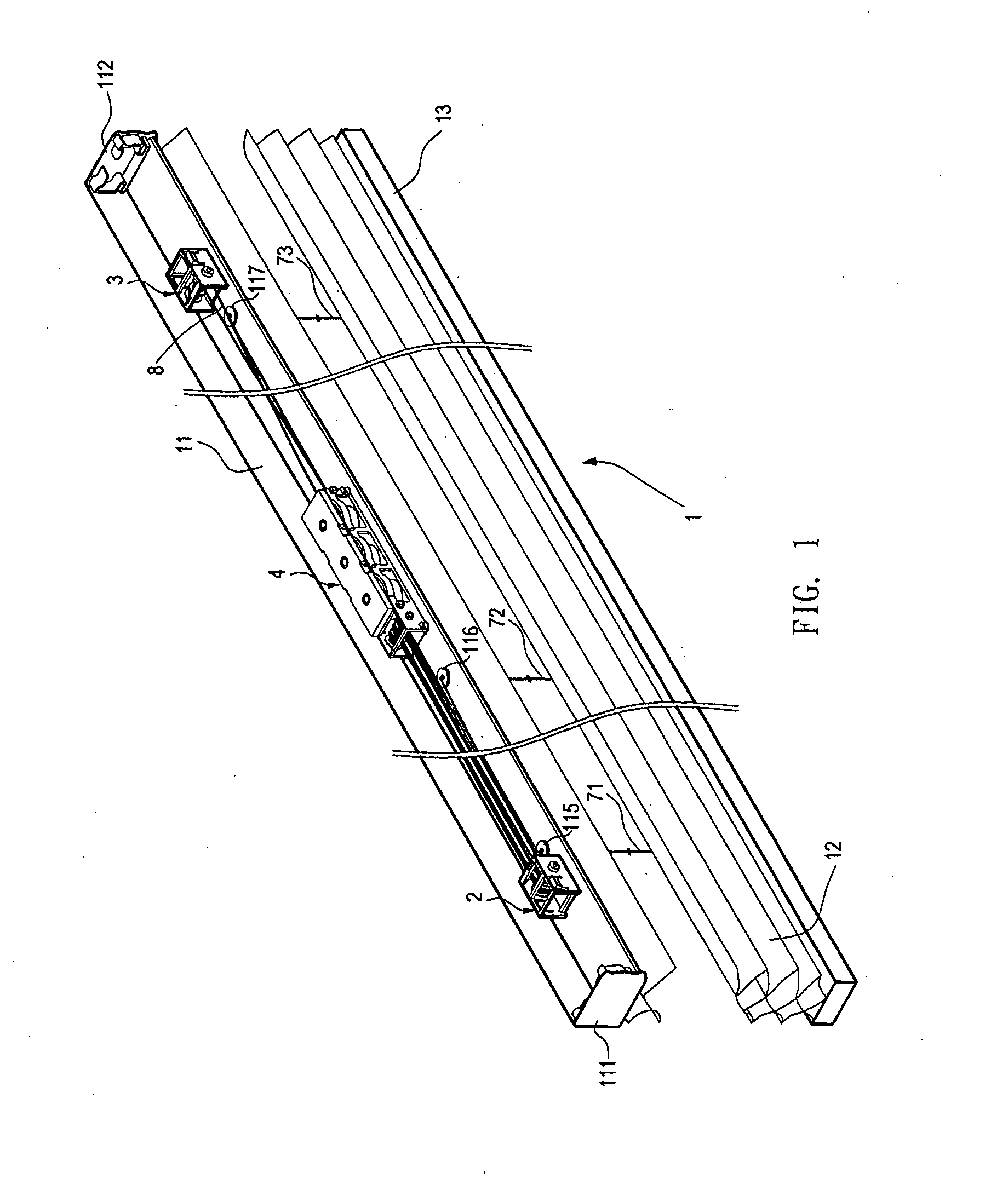
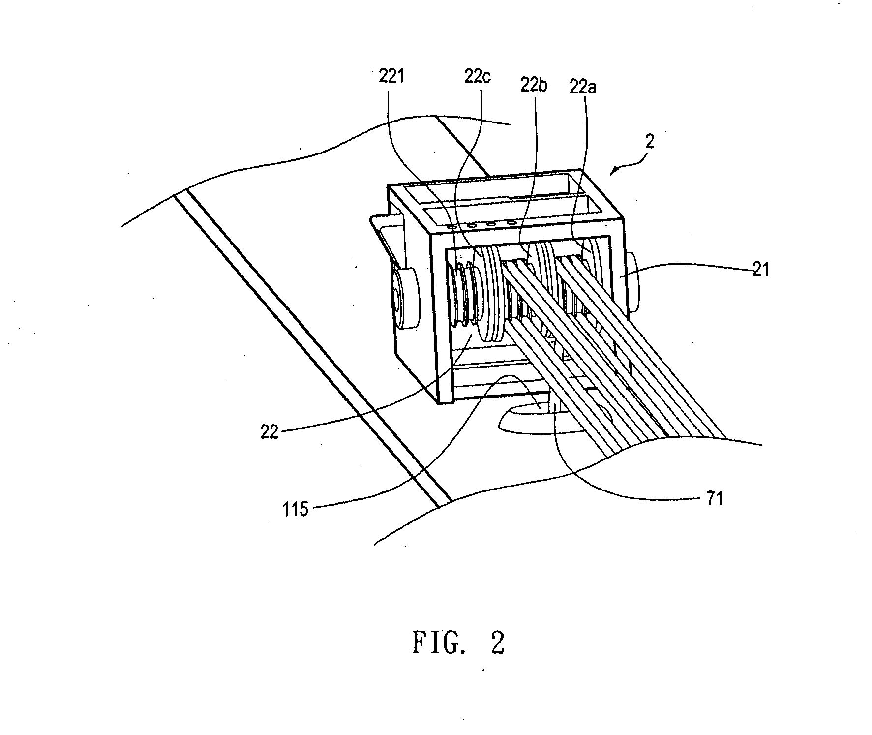
[0031]Referring to FIGS. 1 and 2, they are perspective views of a preferred embodiment of the present invention. A cordless window blind structure 1 includes a head rail 11, a first positioning element 2, a second positioning element 3, a movable seat 4, a blind body 12, a bottom rail 13, three lift cords 71, 72, and 73, and a retrieving cord 8.

[0032]The top end of the head rail 11 has an opening structure and has a predetermined length. The left and right ends of the head rail are respectively formed into a first end and a second end, and end caps 111 and 112 may be respectively disposed on the first and second ends of the head rail 11. The head rail 11 has three through holes 115, 116, and 117 disposed at a bottom portion thereof and they are correspondingly provided for the lift cords 71, 72, and 73 to pass through. The first positioning element 2 is fixe...


PUM


Abstract

A cordless window blind structure is provided. A movable seat having a pulley block and a cord-winding assembly is disposed within a head rail of the cordless blind. The pulley block is connected to a lift cord wound through a first positioning element, so as to control the opening and closing of a blind body. And the cord-winding assembly has a cord winder attached to one end of a retrieving cord and a torsion spring. The other end of the retrieving cord is fastened either on the head rail, the movable seat, a second positioning element, or an end cap. The structure of the second positioning element is resembled to the first positioning element. By taking one end of the retrieving cord as a pivot, the movable seat moves laterally therealong the head rail by a restoring force generated through the torsion spring.

Description

BACKGROUND OF THE INVENTION[0001]1. Field of the Invention[0002]The present invention relates to a cordless window blind structure, and more particularly to a structure which allows greater extent of head rail cut-down on both distant ends and meanwhile increases the drop length of the window blind.[0003]2. Description of Related Art[0004]A conventional window blind structure is usually formed by a blind body, a driving assembly, and a pull cord. In operation, a user must draw the pull cord as a means to open or close the window blind to a desirable position. However, the small frictional surface of the pull cord tends to rub against the hands exerting force thereon, and thus hurting the area of hands contacting with it. Besides, in case of an excessive down-pulling force exerted onto the pull cord or a sudden release at a great speed, the blind body cannot be accurately positioned in a desirable position and the adjustment process must be repeated over again, which is quite inconve...

Claims


Application Information

Patent Timeline
Patent Type & Authority Applications(United States)
IPC IPC(8): E06B9/322
CPCE06B9/322
Inventor WEN, YU-CHECHANG, CHIH-YAO
Owner NIEN MADE ENTERPRISE CO LTD
Why Eureka
Try Eureka