Method of treating water with chlorine dioxide

a technology of chlorine dioxide and water treatment, applied in the direction of biocide, water treatment parameter control, specific water treatment objectives, etc., can solve the problem of relatively high time-specific generation rate of chlorine dioxide, inability to store chlorine dioxide in compressed form or in solutions of relatively high concentration, and hazards in the vicinity of generation systems. , to achieve the effect of saving and improving efficiency

Inactive Publication Date: 2009-06-25
INFRACOR
View PDF6 Cites 24 Cited by
  • Summary
  • Abstract
  • Description
  • Claims
  • Application Information

AI Technical Summary

Benefits of technology

[0026]Accordingly, one object of the present invention is therefore to design the treatment of water with chlorine dioxide so as to be safer and more efficient.
[0027]An additional object of the present invention is, at a high time-specific generation rate of the chlorine dioxide methods, to minimize the hazard potential of this type of water treatment and simultaneously to reduce the expenditure on the safety installations.

Problems solved by technology

Due to the explosive tendency of gaseous chlorine dioxide (c>300 g / m3) and chlorine dioxide solutions (c>26 g / l), chlorine dioxide cannot be stored in compressed form or in solutions of relatively high concentration.
Despite the use of these procedures, in the event of incorrect operation of the chlorine dioxide generation systems, e.g. due to loss of dilution water or by failure of pressure control, spontaneous decomposition (explosion) of chlorine dioxide can occur, or chlorine dioxide may, due to leakage or breakage of separation surfaces between the chlorine-dioxide-containing solution and the environment, lead to hazards in areas surrounding the generation systems.
The use of diluted starting chemicals which leads to chlorine dioxide solutions of a concentration of less than 6 g / l, and therefore the sacrifice of relatively high time-specific generation rates of the chlorine dioxide systems, also cannot exclude hazard to the surrounding areas of the generation systems by exceeding the MAK value [maximum workplace concentration] of 0.1 ppm in the event of incorrect operation.

Method used


Image

  • Method of treating water with chlorine dioxide
  • Method of treating water with chlorine dioxide
  • Method of treating water with chlorine dioxide

Examples


example 1

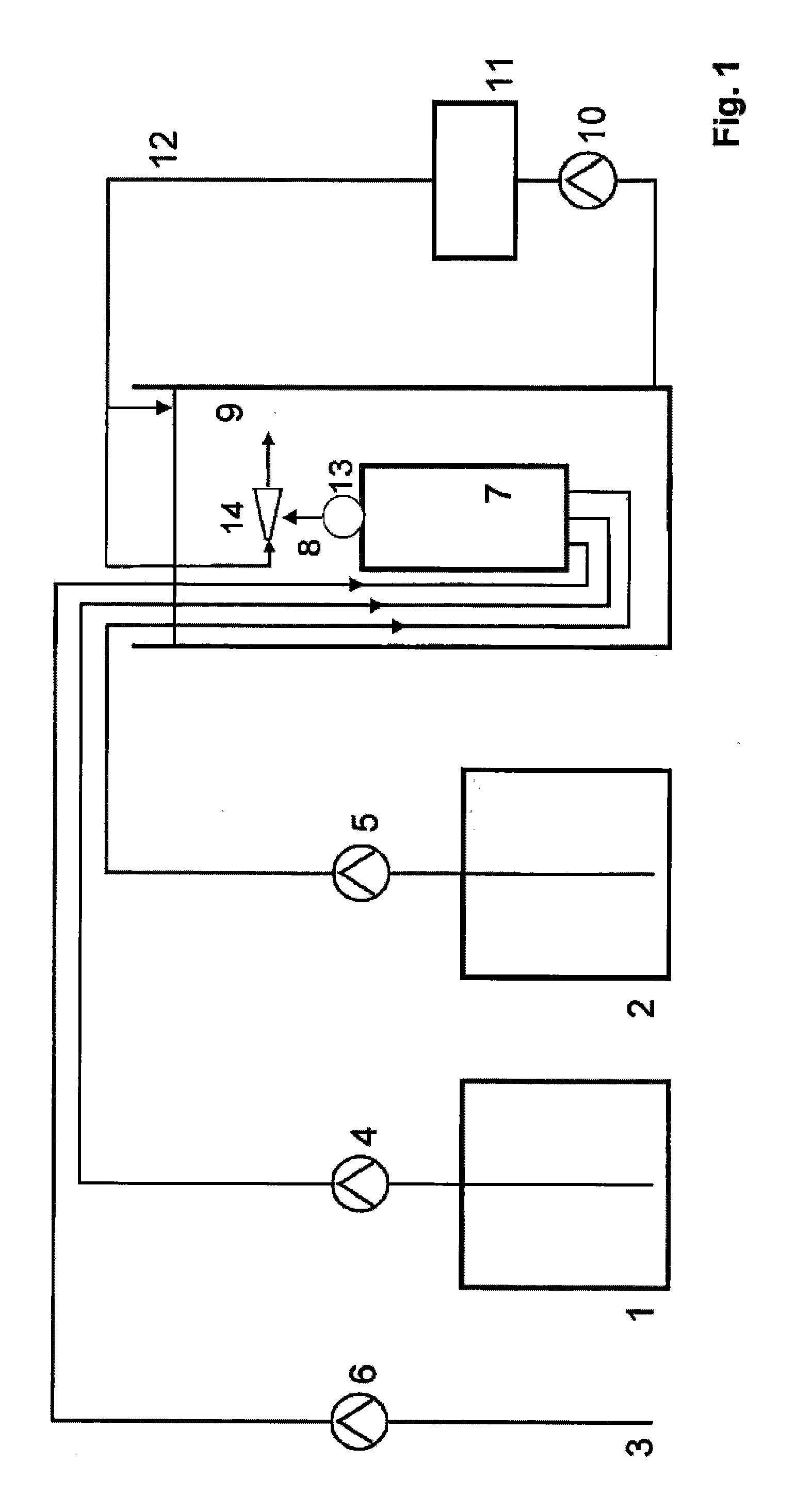
[0086]The device described in FIG. 1 is used. The aqueous solution in the chlorite storage tank 1 contains 25% sodium chlorite and 2.5 l / h of this solution are passed by the transport pump 4 into the reactor 7. From the acid storage tank 2, 2.5 l / h of a 32% strength aqueous hydrochloric acid solution are simultaneously fed to the reactor 7 by the transport pump 5. Via the dilution water rate of 5 l / h, which is likewise simultaneously fed to the reactor 7 from the water connection 3 by the transport pump 6, the concentration of the resultant chlorine dioxide solution is set to 42 g / l [at a yield of 92%]. The reactor has a free volume of 0.33 litres and the residence time of the reaction mixture in the reaction chamber is 2 minutes. 10 litres of chlorine dioxide solution having a content of 42 g / l are fed per hour via the reactor outlet 8 to a water-jet liquid pump 14 which is operated with the water which is to be treated and subsequently mixed with the returned amount of water which...

example 2

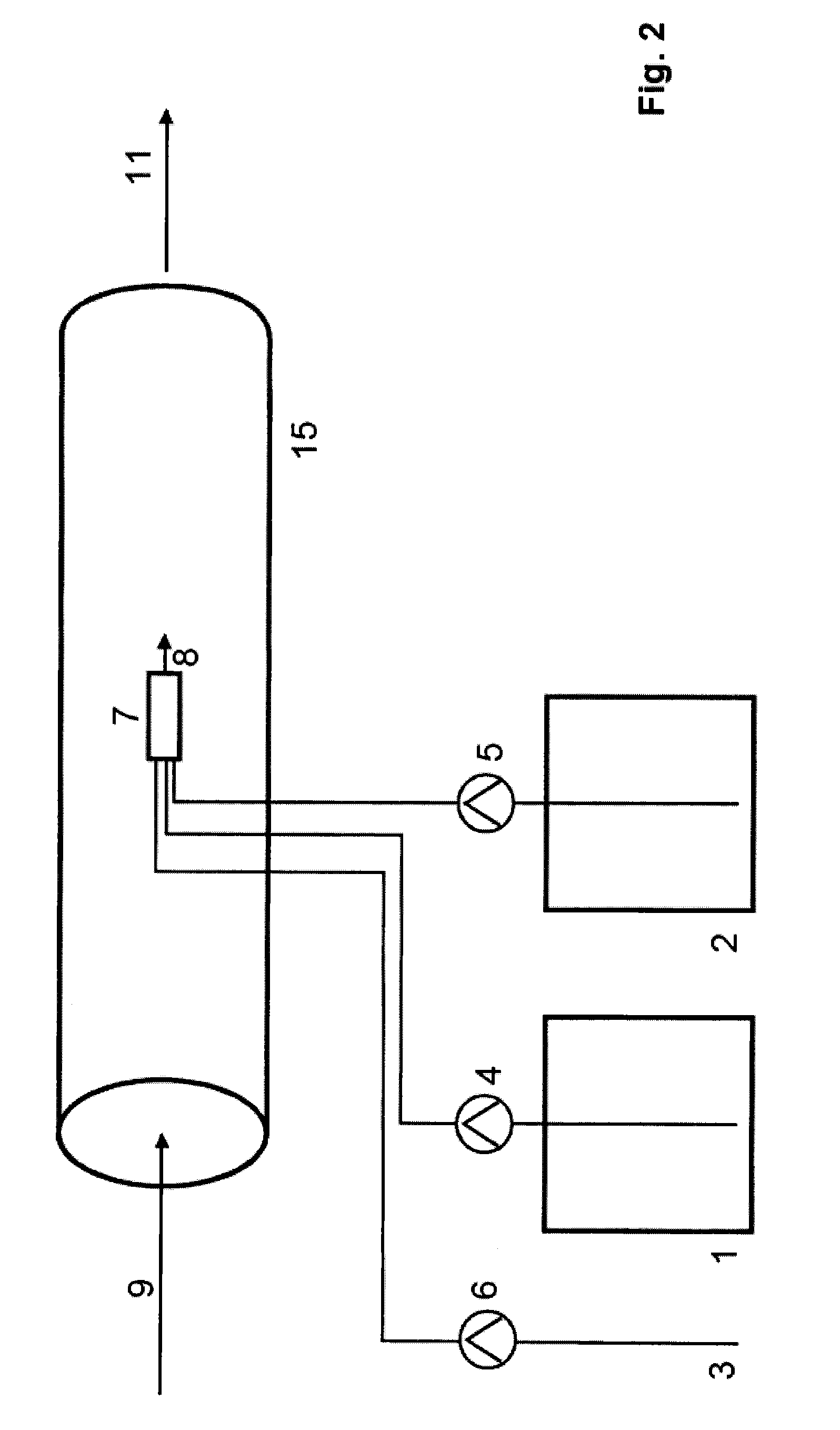
[0087]The device described in FIG. 2 is used. The aqueous solution in the chlorite storage tank 1 contains 25% sodium chloride and 6 l / h of this solution are passed into the reactor 7 by the transport pump 4. From the acid storage tank 2, 5 l / h of a 30% strength aqueous hydrochloric acid solution are simultaneously fed to the reactor 7 by the transport pump 5. The reactor 7 is built into a pipe 14 through which an amount of 100 m3 of water to be treated 9 flows per hour. No dilution water is fed to the reactor via transport pump 6. The reactor has a free volume of 0.075 litres and the residence time of the reaction mixture in the reaction chamber is 0.4 minutes. 11 litres of chlorine dioxide solution having a content of 94 g / l are delivered per hour via the reactor outlet 8 into the water which is to be treated 9 flowing around the reactor 7, as a result of which the concentration of the reaction mixture at the reactor outlet 8 is abruptly reduced to 10 mg / l by mixture with the wate...

example 3

[0088]The device described in FIG. 1 is used. The aqueous solution in the chlorite storage tank 1 contains 24.5% sodium chlorite and 5 l / h of this solution are passed into the reactor 7 by the transport pump 4. From the acid storage tank 2, 5 l / h of a 32% strength aqueous hydrochloric acid solution are simultaneously fed to the reactor 7 by the transport pump 5. Via the dilution water rate of 28 l / h which is likewise simultaneously fed to the reactor 7 from the water connection 3 by the transport pump 6, the concentration of the resultant chlorine dioxide solution is set to 19.7 g / l [at a yield of 83%]. The reactor has a free volume of 6 litres and the residence time of the reaction mixture in the reaction chamber is 9.5 minutes. 38 litres of chlorine dioxide solution having a content of 19.7 g / l are delivered via the reactor outlet 8, which is situated in the vicinity of the suction line of the circulation pump 10, into the water to be treated 9 which surrounds the reactor. 2000 m3...


PUM

PropertyMeasurementUnit
concentrationaaaaaaaaaa

Abstract

A method of treating water with chlorine dioxide (ClO2), by:surrounding a reaction chamber, in which the ClO2 is generated, with water, wherein the water surrounding the reaction chamber is simultaneously the water to be treated; and passing a reaction solution comprising the ClO2 formed in the reaction chamber out of the reaction chamber through an outlet directly into the water, thus treating the water.

Description

BACKGROUND OF THE INVENTION[0001]1. Field of the Invention[0002]The invention relates to a method of treating water with chlorine dioxide (ClO2).[0003]2. Description of the Related Art[0004]Chlorine dioxide is used in water treatment because of its high bactericidal, virucidal and algicidal activity. Due to the explosive tendency of gaseous chlorine dioxide (c>300 g / m3) and chlorine dioxide solutions (c>26 g / l), chlorine dioxide cannot be stored in compressed form or in solutions of relatively high concentration. Owing to these chemical properties, chlorine dioxide must be produced at the point of use. This is conventionally achieved by mixing basic chemicals in special reactors of chlorine dioxide generation systems. The chemical storage vessels, the metering appliances and also the reactor of the chlorine dioxide systems form a locally linked unit of apparatus which is generally erected in rooms accessed by people.[0005]There are a plurality of methods for synthesizing ClO2 ...

Claims


Application Information

Patent Timeline
Patent Type & Authority Applications(United States)
IPC IPC(8): C02F1/76
CPCA01N59/00C01B11/024C02F1/76C02F2103/023C02F2209/05C02F2303/04C02F2209/003C02F1/50
Inventor DUVE, HANS
Owner INFRACOR
Why Eureka
Try Eureka