Butt Welding System of Steel Plate and Butt Welding Method of Steel Plate

a welding system and butt welding technology, applied in the direction of soldering equipment, manufacturing tools, auxillary welding devices, etc., can solve the problems of increased facility and manufacturing costs, welding defects, and possible welding defects, so as to ensure the quality of a produ

Inactive Publication Date: 2009-06-25
TOYOTA JIDOSHA KK
View PDF4 Cites 29 Cited by
  • Summary
  • Abstract
  • Description
  • Claims
  • Application Information

AI Technical Summary

Benefits of technology

[0026]A butt welding system and butt welding method can be provided by which the quality of a product can be ensured.

Problems solved by technology

For example, when blanked steel plates (hereinafter referred to as blank members) are butted together and butting portions of these blank members (hereinafter simply referred to as butting portions) are radiated with laser light for butt welding of the blank members to obtain a tailored blank member, if a gap of the butting portions is larger than an allowance value (the magnitude of an allowable gap), a welding defect may occur, such as a pinhole.
Although linear precision of each butting portion of each blank member can be increased also through a cutting process using a laser, facility and manufacturing costs are increased.
However, in the butt jointing device according to Patent document 1, when relatively large projections and recesses and burrs are present on a butting portion of any blank member, a gap occurs in the butting portion when the butting load is released, thereby possibly causing a welding defect, such as a pinhole, on the butting portion.
Moreover, in the butt jointing device of this type, a clamp device that holds the blank members is dedicatedly manufactured in accordance with the shape of each blank member, and therefore there is a problem in general versatility.
To get around this, a plurality of clampers each driven by an air cylinder may be disposed along the butting portion, but many air cylinders are required, thereby increasing manufacturing cost.
However, since measurement takes some time (10 to 60 seconds), no laser output can be measured for each product in view of problems of productivity, and a large number of products with welding defects may have been manufactured at the time of discovering a problem with laser output.
However, since image processing takes some time, pinhole detection and welding cannot be simultaneously performed, and pinhole detection is performed exclusively in an examining process after welding under present circumstances.

Method used


Image

  • Butt Welding System of Steel Plate and Butt Welding Method of Steel Plate
  • Butt Welding System of Steel Plate and Butt Welding Method of Steel Plate
  • Butt Welding System of Steel Plate and Butt Welding Method of Steel Plate

Examples


Embodiment Construction

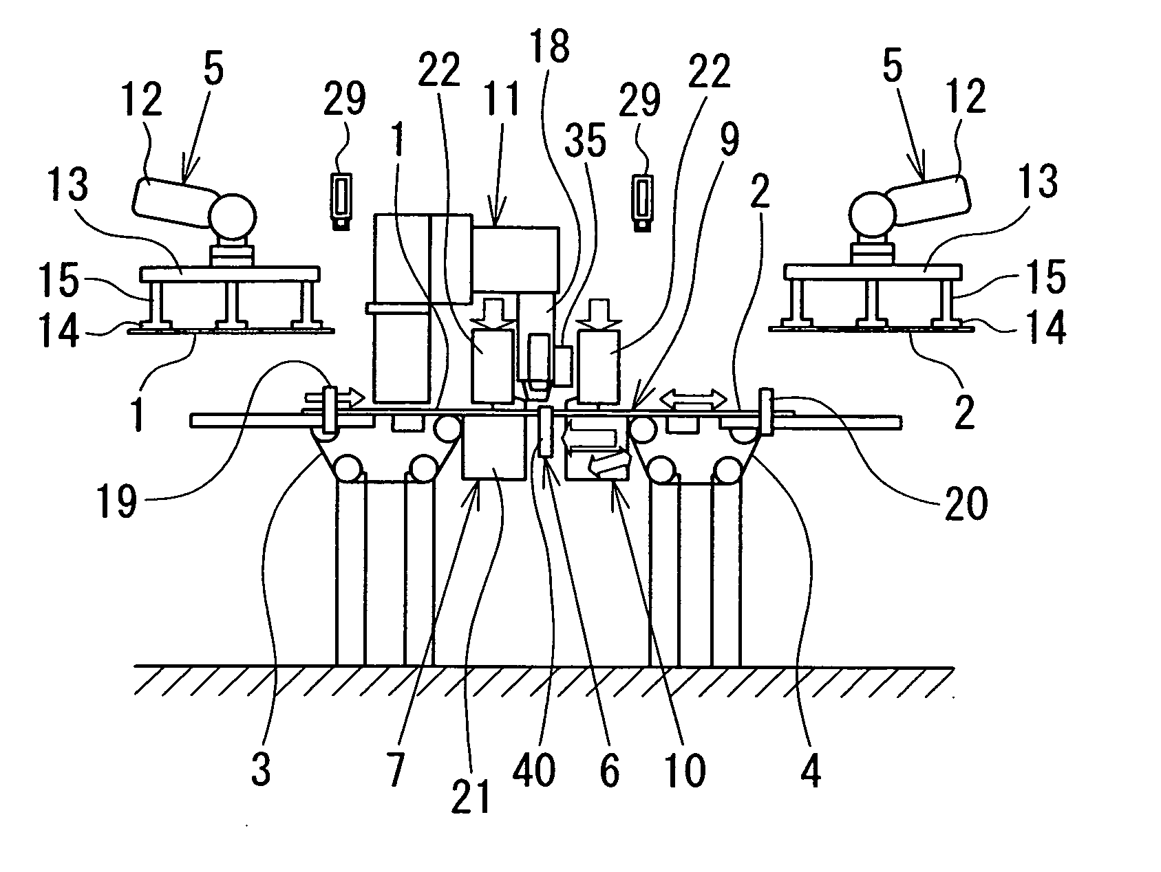
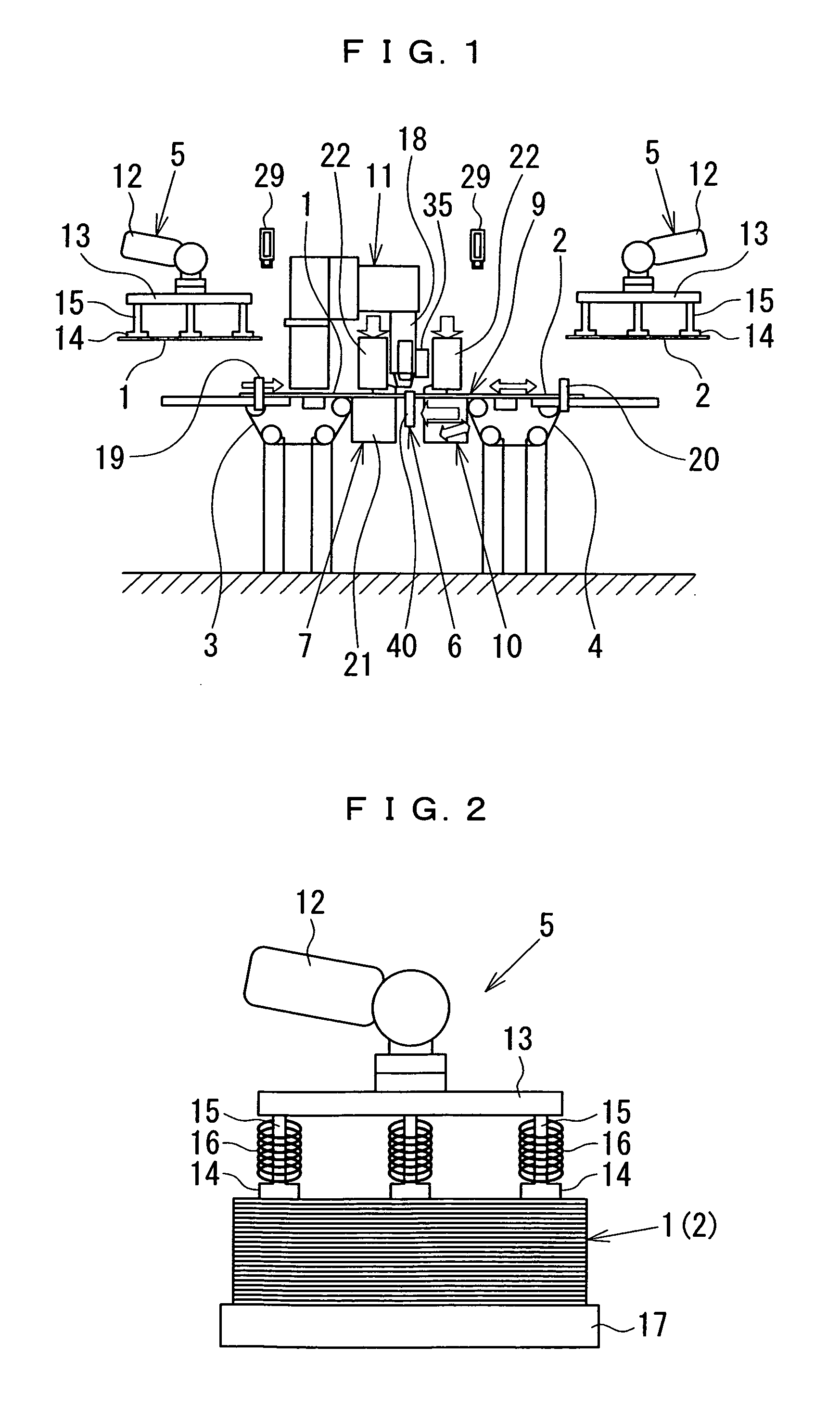
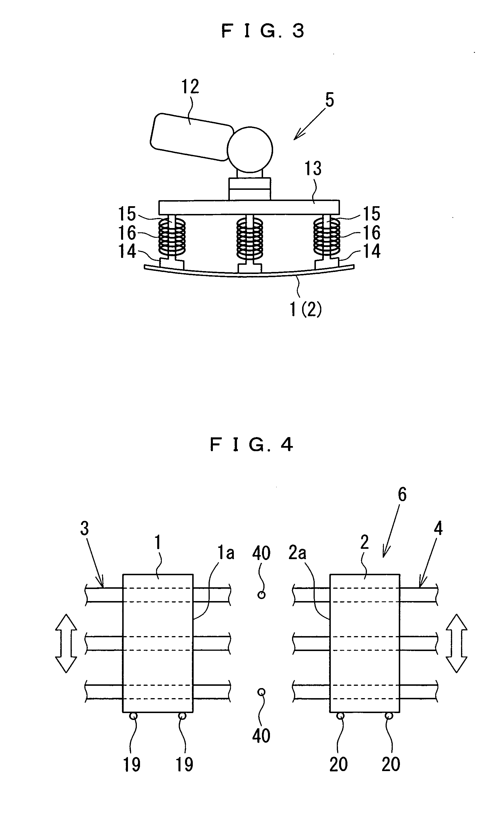
[0044]An embodiment of the present invention is described based on FIGS. 1 to 14. As depicted in FIG. 1, the present butt welding system includes a workpiece supply device 5 in which blank members 1, 2 (steel plates) are supplied (loaded) one by one onto magnet conveyers 3, 4, respectively; a workpiece positioning device 6 by which the blank members 1, 2 loaded on the magnet conveyers 3, 4, respectively are positioned at their predetermined position; a workpiece gripping device 7 (gripping means 7) by which the blank members 1, 2 positioned by the workpiece positioning device 6 are gripped near butting portions 1a, 2a of the blank members 1, 2, respectively; a workpiece butting device 9 (butting means) by which the blank members 1, 2 gripped by the workpiece gripping device 7 are butted at their butting portions 1a, 2a, respectively and a predetermined butting load is applied to a butting portion 8 of the blank members 1, 2; a workpiece matching device 10 (matching means) by which t...


PUM

PropertyMeasurementUnit
moving distanceaaaaaaaaaa
frequencyaaaaaaaaaa
frequencyaaaaaaaaaa

Abstract

A butt welding system and a butt welding method of steel plate by which the quality of a product can be ensured. Butting portions of blank members (1,2) to be joined together are butted and a predetermined butting load is applied to the butting portion, wherein the blank members (1,2) are moved relatively in the direction of the welding line thus matching the butting portions. Protrusions and recesses formed on each butting portion of each blank member (1,2) are flattened, whereby linear precision at each butting portion of each blank member (1,2) is enhanced as compared with a case where the butting portions are not matched. Since the gap is reduced extremely at the butting portion, welding is facilitated at the butting portion. Good welding beads are thereby obtained at the butting portion and the quality of a product is ensured.

Description

TECHNICAL FIELD[0001]The present invention relates to butt welding systems of steel plate and butt welding methods of steel plate and, in particular, to a butt welding system of steel plate and a butt welding method of steel plate for butt-welding of blanked steel plates.BACKGROUND ART[0002]Conventionally, in automobile outer-panel components and others, tailored blank members have been used that are formed by jointing steel plates different from each other in plate thickness and mechanical characteristics, in order to reduce the weight of a vehicle body and improve collision safety performance. For example, when blanked steel plates (hereinafter referred to as blank members) are butted together and butting portions of these blank members (hereinafter simply referred to as butting portions) are radiated with laser light for butt welding of the blank members to obtain a tailored blank member, if a gap of the butting portions is larger than an allowance value (the magnitude of an allo...

Claims


Application Information

Patent Timeline
Patent Type & Authority Applications(United States)
IPC IPC(8): B23K26/00B23K26/21B23K37/04
CPCB23K26/03B23K26/26B23K2203/04B23K2201/18B23K37/0408B23K2101/18B23K2103/04
Inventor NISHIO, MASAHIROTANZAWA, MASAKIHIDA, MASAKOSHIMIZU, TAKAYUKIKASHIWABARA, KEIICHISAKEMI, SHUUJI
Owner TOYOTA JIDOSHA KK
Why Eureka
Try Eureka