

Boost converter with adaptive coil peak current
a peak current and boost converter technology, applied in the direction of automatic control, process and machine control, instruments, etc., can solve the problems of inefficient operation of pfm controllers, and inefficiency of operation under lighter load conditions
- Summary
- Abstract
- Description
- Claims
- Application Information
AI Technical Summary
Benefits of technology
Problems solved by technology
Method used
Image

Examples
Embodiment Construction
[0036]Although particular embodiments are described herein, other embodiments, including embodiments that do not provide all of the benefits and features set forth herein, will be apparent to those of ordinary skill in the art.
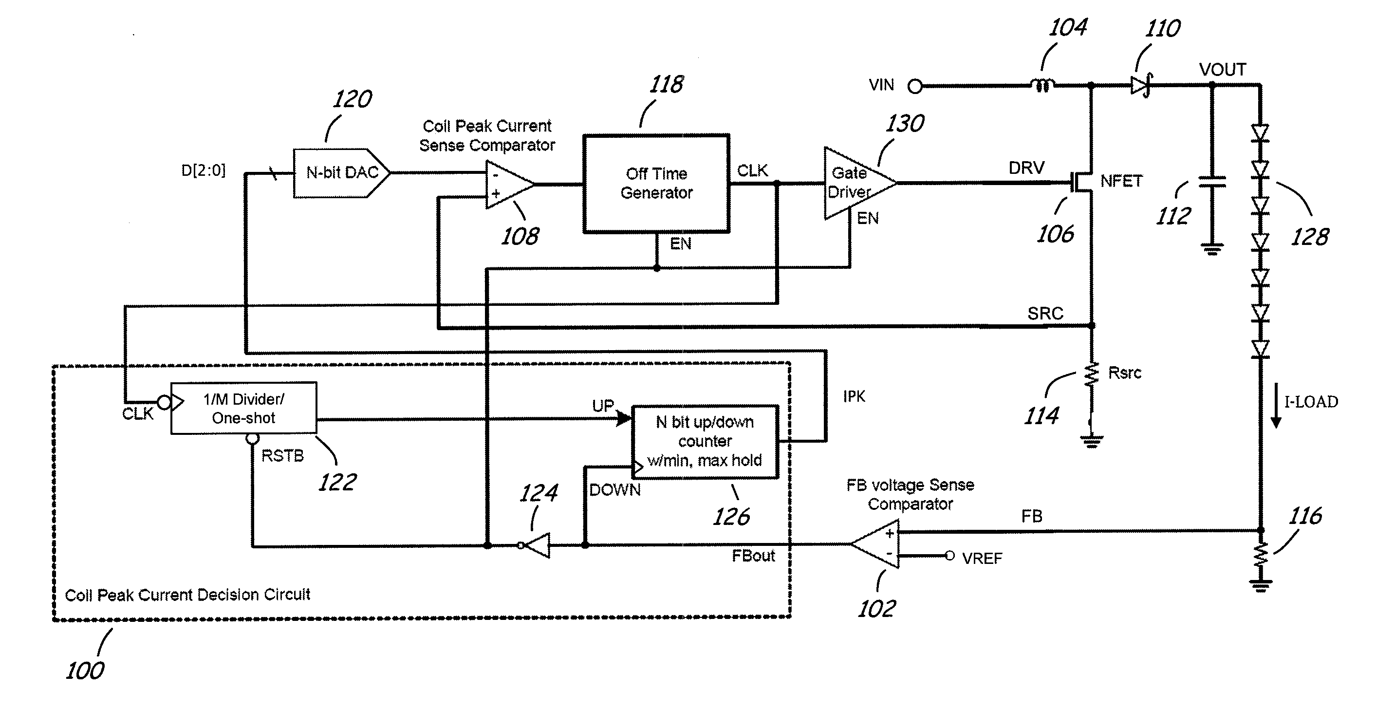
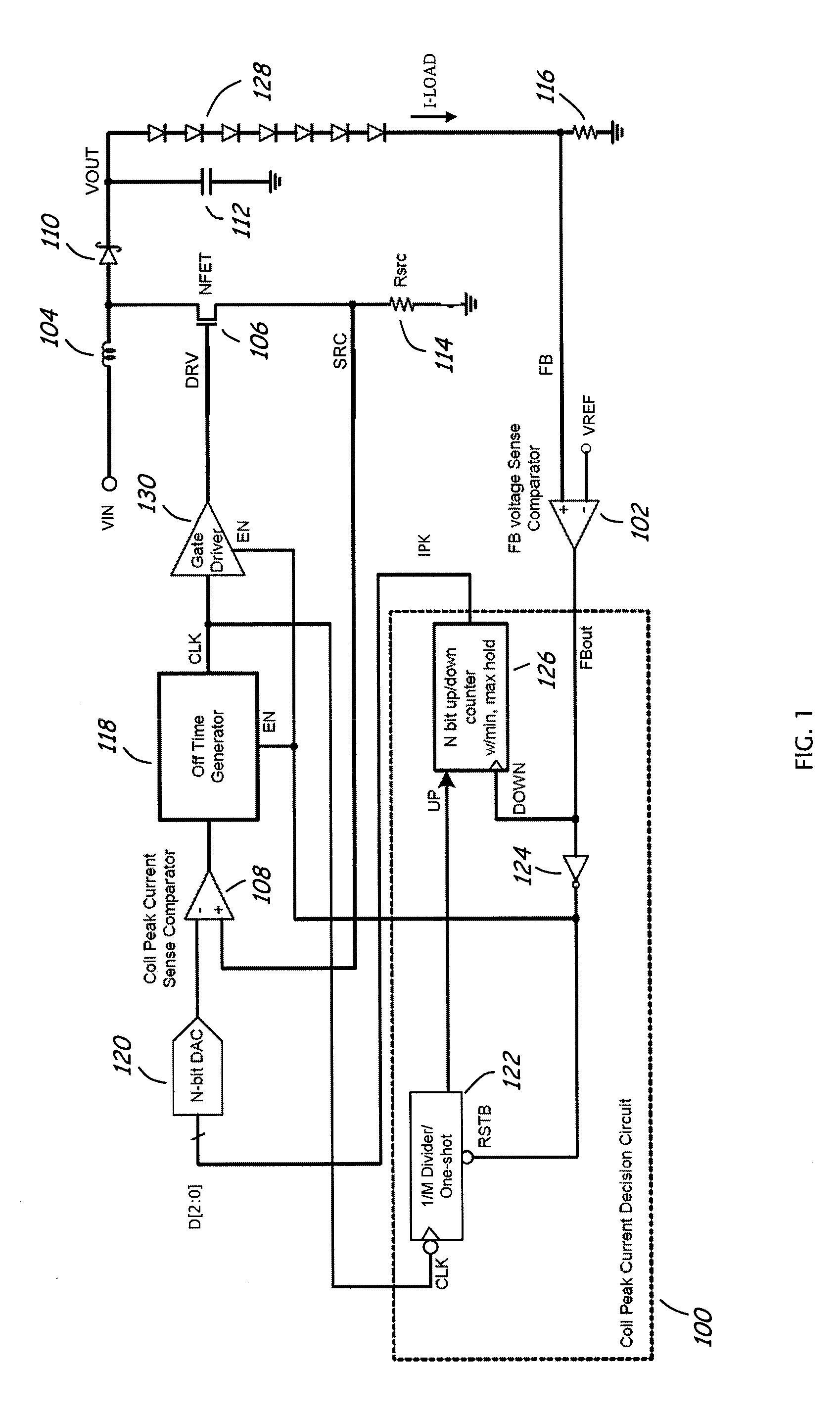
[0037]FIG. 1 is a simplified circuit diagram for one embodiment of a power converter in accordance with the present invention. By way of example, the power converter is a current mode boost converter that accepts a substantially DC input voltage (VIN) and produces a substantially DC output voltage (VOUT) which can be greater than the input voltage. The output voltage can be used to power a load 128, e.g., a plurality of light emitting diodes (LEDs) connected in series or a string of LEDs. The boost converter can adjust the brightness of the LEDs by varying the power (or load current) provided to the load 128. In some applications, the load current (I-LOAD) varies over a wide range to accommodate a wide range of ambient lighting conditions and / or user preferenc...
PUM
| Property | Measurement | Unit |
|---|---|---|
| Time | aaaaa | aaaaa |
| Current | aaaaa | aaaaa |
| Frequency | aaaaa | aaaaa |
Abstract
Description
Claims
Application Information