System and method for measuring antenna radiation pattern in fresnel region

a radiation pattern and antenna technology, applied in the field of system and method for measuring antenna radiation pattern in fresnel region, can solve the problems of demerit of method, difficult to maintain a secret, interference and problem between conventional communication services, etc., and achieve the effect of reducing cost, improving utility of installed reference antennas, and reducing costs

Inactive Publication Date: 2009-06-25
ELECTRONICS & TELECOMM RES INST
View PDF9 Cites 26 Cited by
  • Summary
  • Abstract
  • Description
  • Claims
  • Application Information

AI Technical Summary

Benefits of technology

[0012]The present invention as mentioned above reduces a cost by manually moving a movable antenna upward or downward. Although the present invention implements the movable antenna automatically by using a motor, the present invention reduces a cost since a movable shaft is perpendicular.
[0013]Moreover, the present invention improves utility of an installed reference antenna since a partner antenna (generally, a reference horn antenna or a reference dipole antenna) of the antenna to be measured does not need a high directivity.

Problems solved by technology

However, the field measuring method is sensitive to weather, and may generate an interference and problem between conventional communication services.
Moreover, in a case of an antenna for a military or a security, the field measuring method has a demerit that it is difficult to maintain a secret by being exposed to a spy satellite.
The compact range method needs a reflector antenna which is expensive and quite difficult to be attached or detached.
The compact range method has problems that it is difficult to install and maintain the reflector since an area of the reflector increases at a low frequency band of hundreds of MHz, and it is difficult to satisfy a process error of μm at a high frequency above 100 GHz when the reflector is manufactured.
However, this method needs a lot of resources since instrument member moving a probe needs precision.
However, this method has some demerits under a real measuring environment.
Firstly, when an angle of a large antenna of dozens kilograms (kg) is changed upward or downward, a safety accident may occur due to the weight of the antenna.
Further, if an angle of the measuring antenna is changed upward or downward, this method may generate a measuring error by receiving all unpreferable reflective waves which are reflected from an absorbing body attached to a bottom plane and a ceiling plane.

Method used


Image

  • System and method for measuring antenna radiation pattern in fresnel region
  • System and method for measuring antenna radiation pattern in fresnel region
  • System and method for measuring antenna radiation pattern in fresnel region

Examples


Embodiment Construction

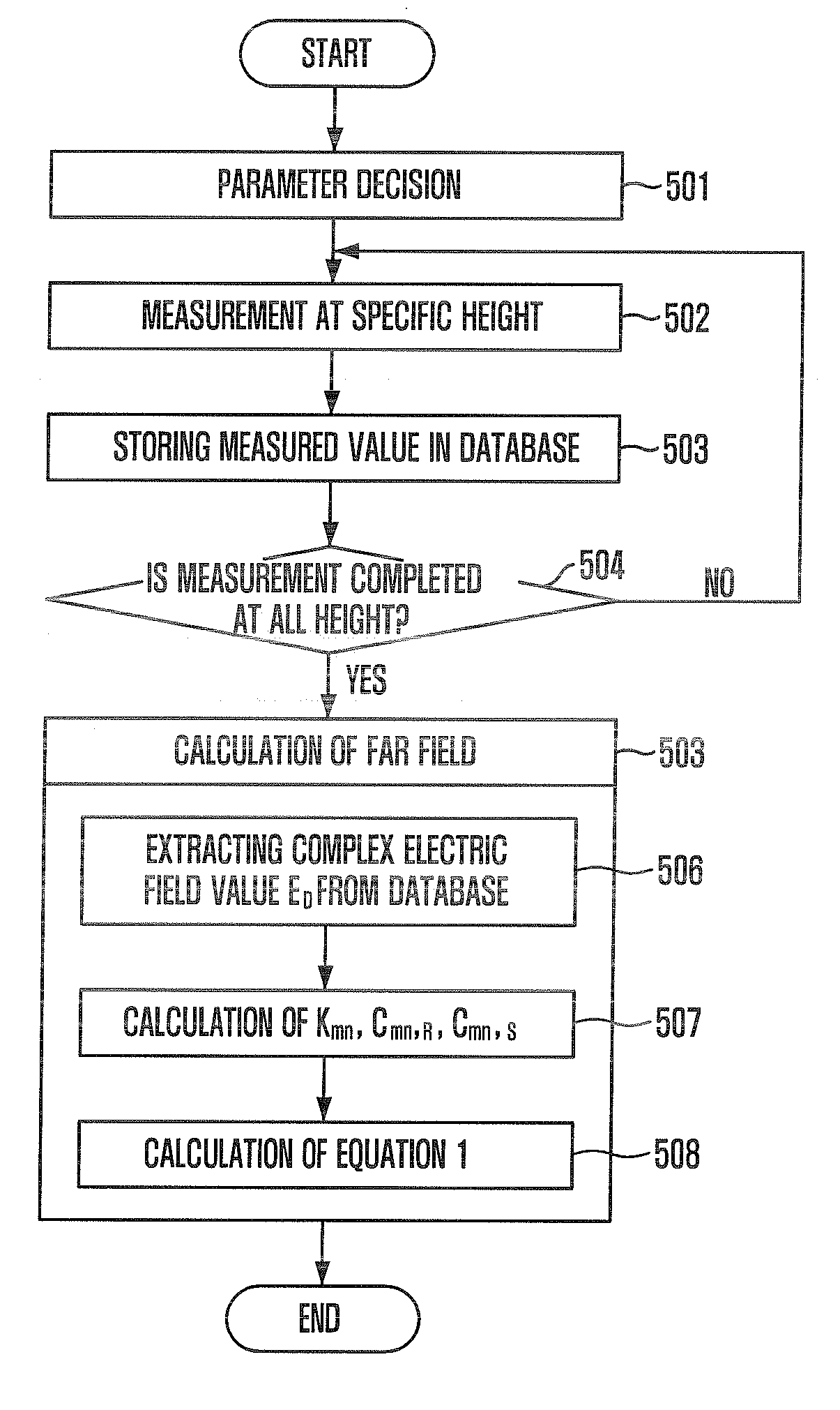
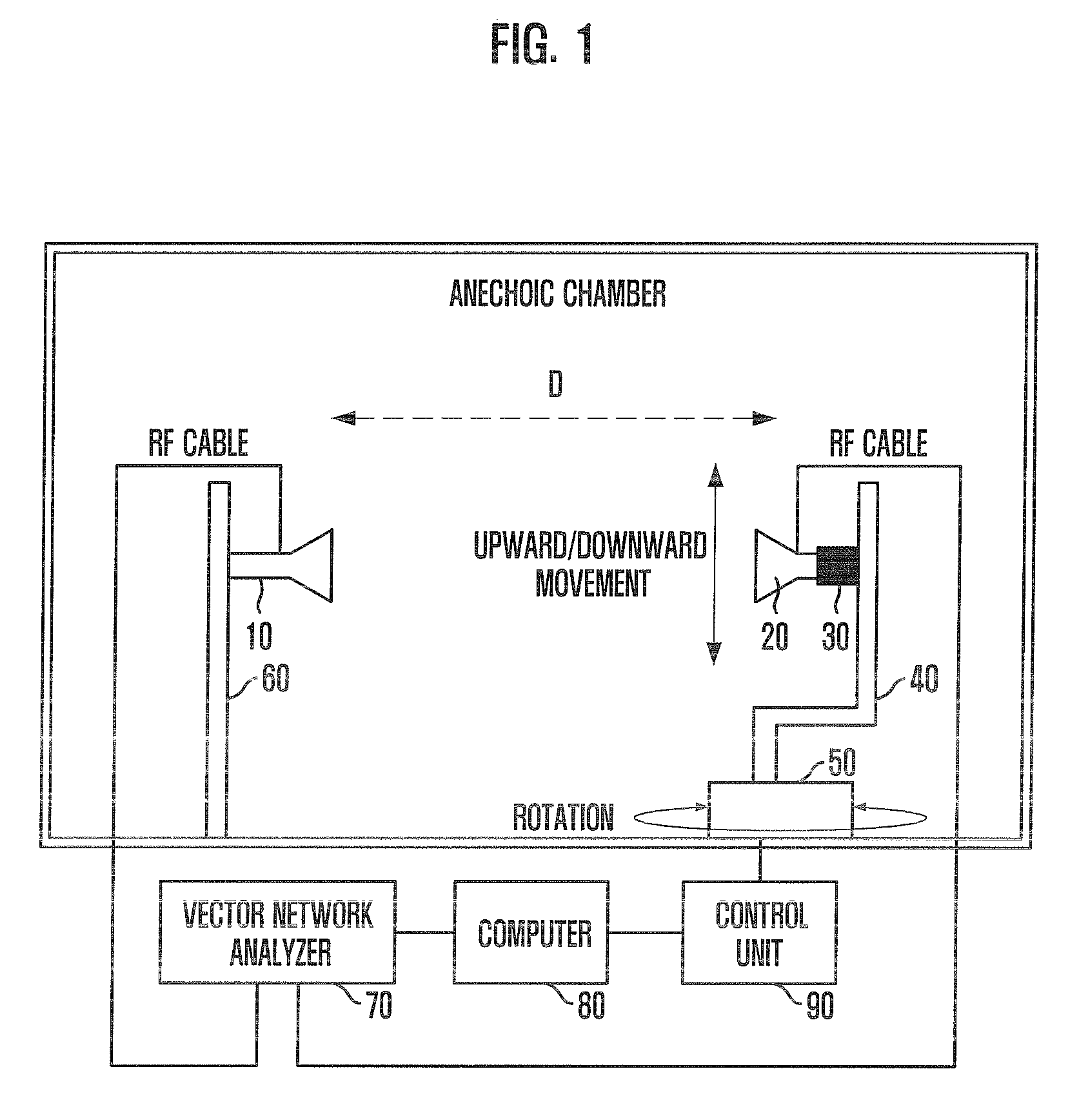
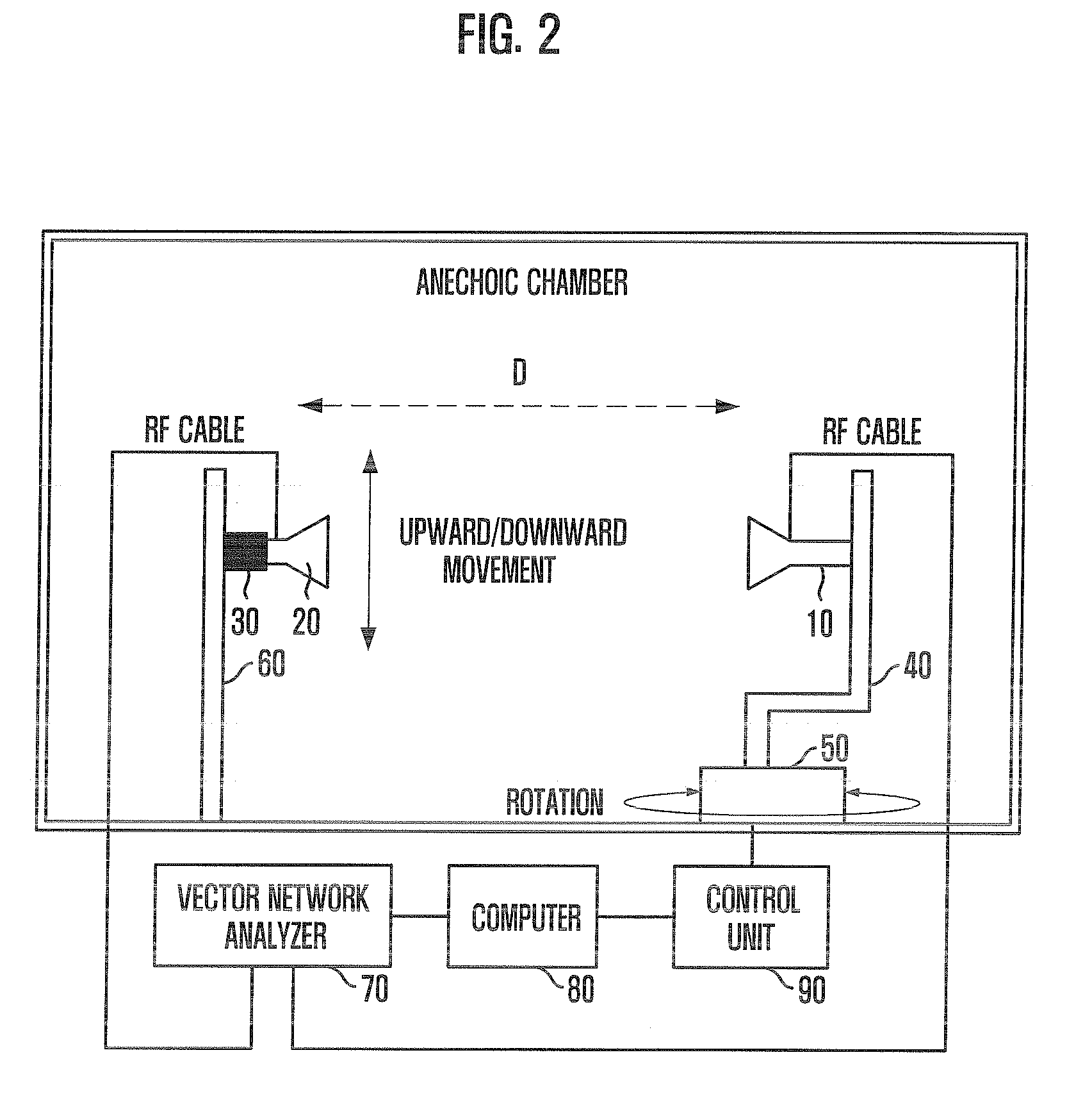
[0021]FIG. 1 is a block diagram of a system for measuring antenna radiation pattern in a Fresnel region in accordance with an embodiment of the present invention and FIG. 2 is a block diagram of a system for measuring an antenna radiation pattern in a Fresnel region in accordance with another embodiment of the present invention.

[0022]The block diagrams shown in FIGS. 1 and 2 are similar to a conventional far-field measuring system since the present invention uses the conventional measuring system as much as possible.

[0023]As shown in FIGS. 1 and 2, a system for measuring an antenna radiation pattern in a Fresnel region includes two measuring antennas (a fixed antenna 10 and a movable antenna 20), a moving device 30, a rotation device 50, a vector network analyzer (hereinafter, called as a ‘VNA’) 70, a computer 80 and a control unit 90. The measuring antennas are installed to be apart from each other as long as a distance D within a Fresnel region in order to acquire a far-field radi...


PUM


Abstract

There is a provided a system for measuring an antenna radiation pattern in a Fresnel region, including: a fixed antenna and a movable antenna located in the Fresnel region to acquire a far-field radiation pattern; a moving unit for moving upward or downward to adjust a measuring angle of the movable antenna; a rotation unit to rotate a rotation shaft horizontally; a vector network analyzing unit for outputting an radio frequency (RF) signal to one of the fixed antenna and the movable antenna as a transmission antenna, receiving the RF signal received through the other one of the fixed antenna and the movable antenna as a receiving antenna, and detecting a complex value; a control and communication unit for controlling the vector network analyzing unit and a control unit, and performing a data communication; and the control unit for providing a vertical / horizontal rotation force to the moving unit and the rotation unit under a control of the control and communication unit.

Description

TECHNICAL FIELD[0001]The present invention relates to a system and method for measuring an antenna radiation pattern in a Fresnel region; and, more particularly, to a system and method for measuring a far distance radiation pattern by changing a measurement height of an antenna upward or downward differently from a conventional process in a Fresnel region as an intermediate region between a far distance and a short distance.BACKGROUND ART[0002]A reflector antenna for a satellite or an array antenna which arrays a plurality of single elements has a larger size than a single antenna about dozens times. Accordingly, a minimum gap distance Rfar between a source antenna and a measuring antenna should satisfy Rfar=2 L2 / λ in order to acquire a far distance radiation pattern. Here, L is a length of an aperture plane of the measuring antenna, and λ is a wavelength of an operating frequency. For example, a minimum gap distance of a far distance radiation pattern of an antenna, which is operat...

Claims


Application Information

Patent Timeline
Patent Type & Authority Applications(United States)
IPC IPC(8): G01R29/10
CPCG01R29/10
Inventor OH, SOON-SOOYUN, JE-HOONMOON, JUNG-ICKKIM, JOUNG-MYOUNCHO, YONG-HEUI
Owner ELECTRONICS & TELECOMM RES INST
Why Eureka
Try Eureka