
Plane focus antenna

Inactive Publication Date: 2009-06-25
NATIONAL TSING HUA UNIVERSITY
View PDF2 Cites 68 Cited by
  • Summary
  • Abstract
  • Description
  • Claims
  • Application Information

AI Technical Summary

Benefits of technology

[0009]By means of the construction set forth above, and through the characteristics of the stacking double split-ring resonator of negative magnetic permeability and the metal wire which has negative electric permittivity, a NRIM can be formed by stacking. Such a material can be used to fabricate a plane focus antenna. NRIM has focus effect like a convex lens. Through the plane focus antenna signals can be converged to a very small area to enhance signal receiving. Moreover, because of the antenna is a plane distortion can be prevented. Because of these features the plane focus antenna of the invention can be made in a small size and light weight.

Problems solved by technology

In addition, in terms of the plane antenna structure, the conventional techniques cannot achieve the effect of converging signals.

Method used


Image

  • Plane focus antenna
  • Plane focus antenna
  • Plane focus antenna

Examples


Embodiment Construction

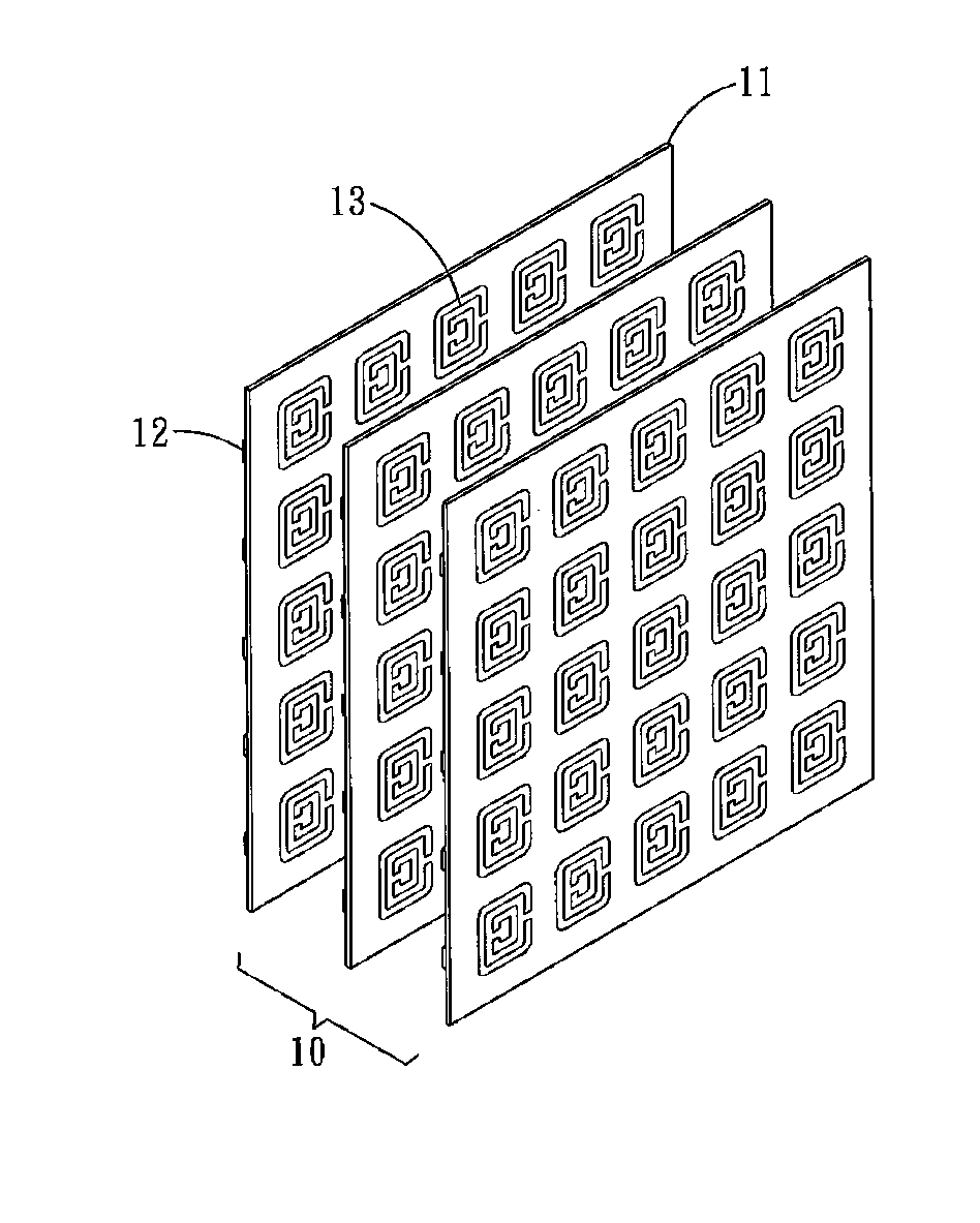
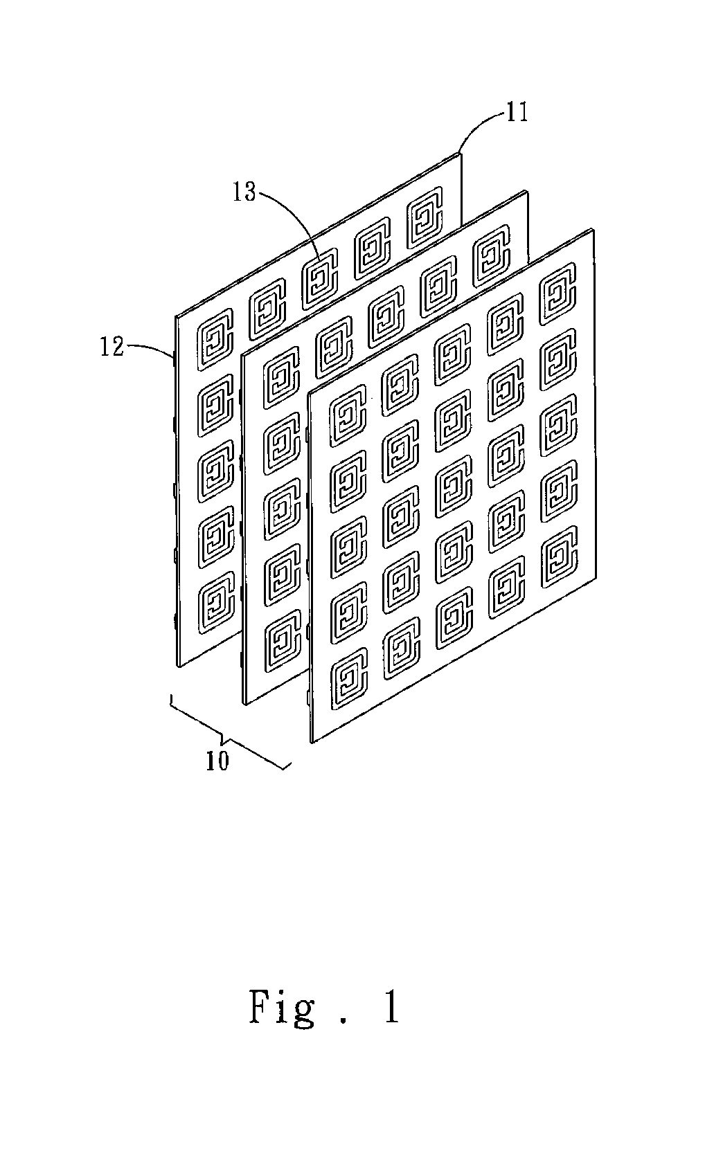
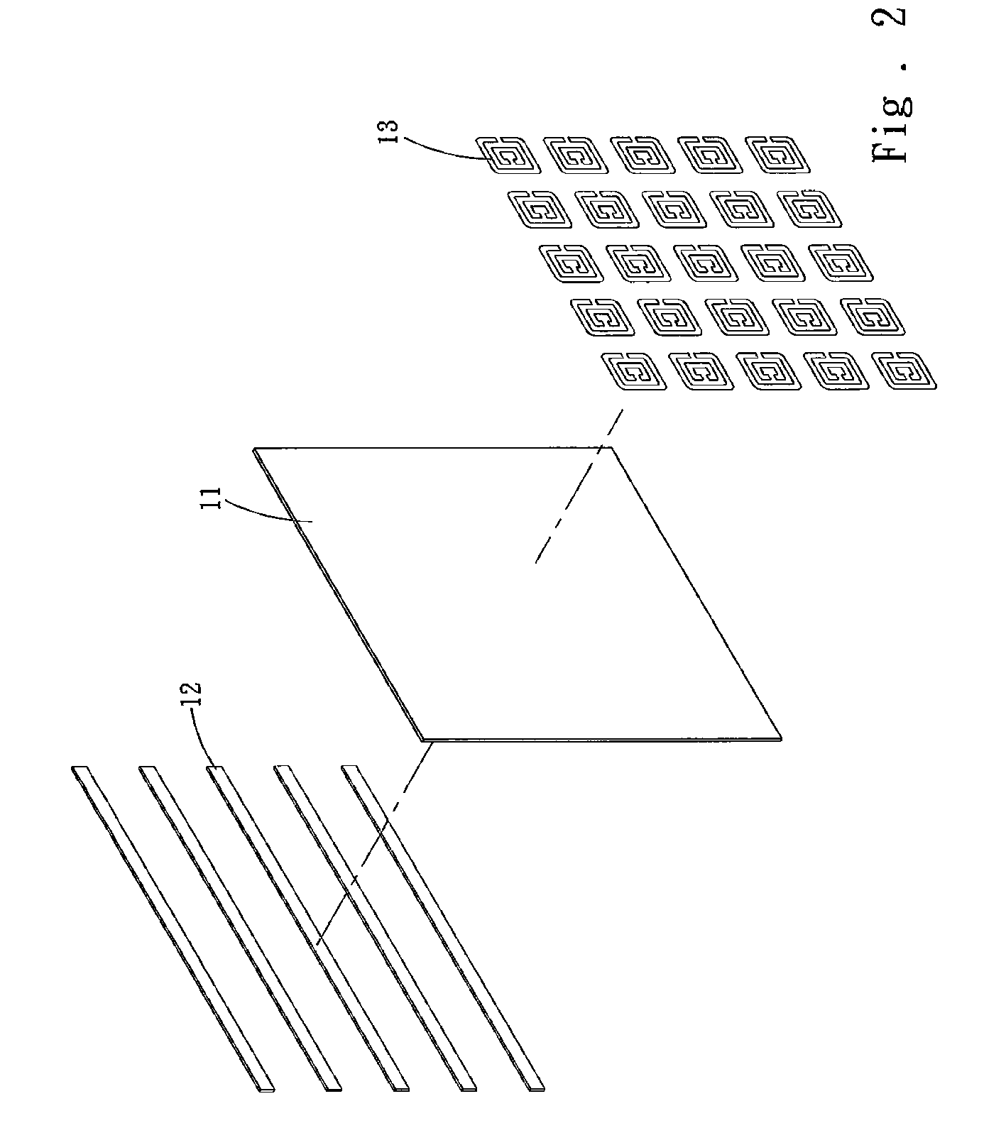
[0016]Please refer to FIGS. 1 and 2, the plane focus antenna 10 according to the invention is formed by stacking a plurality of substrates 11 together. Each of the substrates 11 has one side formed a periodic array plane consisting of a plurality of resonant coils 13 and other side laid with a fine metal wire formed in a periodic structure. The substrates 11 are made from ceramic or glass fibers. The resonant coils 13 are double split-ring resonators made of non-magnetic conductive metal such as gold, silver, copper or aluminum. The fine metal wire 12 is made of metal of a negative electric permittivity and is selected from gold, silver or aluminum.

[0017]Refractive index is very important to the permeability of electromagnetic wave. The refractive index is formed by skewing caused by interactions of electromagnetic wave and electric permittivity and magnetic permeability. However the medium of negative refractive index does not exist in the nature. There is no material in the nature...


PUM


Abstract

A plane focus antenna includes a plurality of stacking substrates. Each substrate has one side formed a periodic array plane consisting of a plurality of resonant coils and other side laid a metal wire formed in a periodic structure. The magnetic permeability of the stacking double split-ring resonators is negative and the electric permittivity of the metal wire is negative at the same time that can interact with electromagnetic waves to fabricate a negative refractive index material (NRIM) to form the plane focus antenna. By means of the special refractive effect of the NRIM receiving signals can be converged in a very small area to enhance the receiving signals. The plane antenna also does not generate distortion.

Description

FIELD OF THE INVENTION[0001]The present invention relates to a plane focus antenna and particularly to a high frequency plane focus antenna made from a negative refractive index material (NRIM) and adopted Snell's law to change incident wave traveling direction to focus the incident wave at a smaller area to form a stronger receiving signal without distortion.BACKGROUND OF THE INVENTION[0002]The rapid advance of wireless communication industry has constantly spawned a wide variety of communication products. Competition is intense. These days the communication products have to be versatile, provide multiple functions and be lean and light. To meet these requirements, demand on antenna also is very high. In 1994 plane focus antenna was announced that is a meandering radiation object formed on a substrate. Such a structure can effectively shrink the length and size of the antenna.[0003]Aside from smaller size, the antenna also has to support multiple frequencies and cover a wide range ...

Claims


Application Information

Patent Timeline
IPC IPC(8): H01Q7/00H01Q11/12
CPCH01Q7/00H01Q15/0086H01Q15/10H01Q15/02
Inventor YEN, TA-JENCHEN, CHENG-KUANG
Owner NATIONAL TSING HUA UNIVERSITY
Learn More