
Eureka
For R&D, Eureka makes reading and utilizing patents & technical documents easy.
Eureka AIR
Designed for self-driven R&D workflows. Generate viable solutions, solve complex R&D challenges, empower your innovation with AI.

Eureka Materials
Designed for material experts only. Revolutionize your material R&D, from search, analyze, to developing new materials.

TechResearch
Generate reliable direction feasibility study reports for your R&D in just a few steps.

TechSeek
Discover and master advanced knowledge NOW. Basics, ideas, possibilities, all at once.

TechMind
As an expert in R&D Theories, TechMind can generates customized viable solutions instantly.

TechRisk
Analyze your overall solution with one click, know your potential R&D risks in advance.

TechMonitor
Get weekly tech updates, stay abreast of the latest tech innovations and key insights.
Zoom lens system
- Summary
- Abstract
- Description
- Claims
- Application Information
AI Technical Summary
Benefits of technology
Problems solved by technology
Method used
Image

Examples
embodiment 1
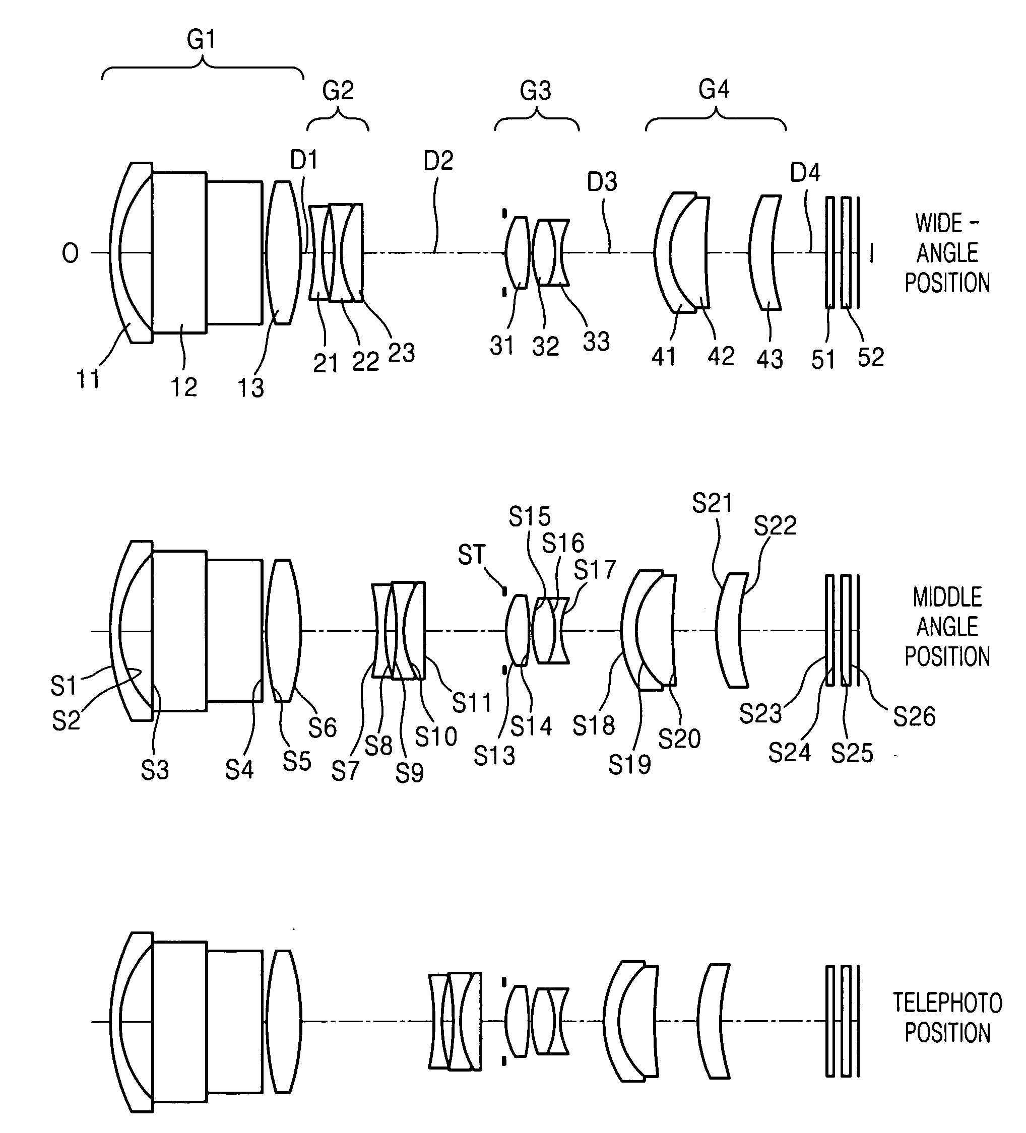
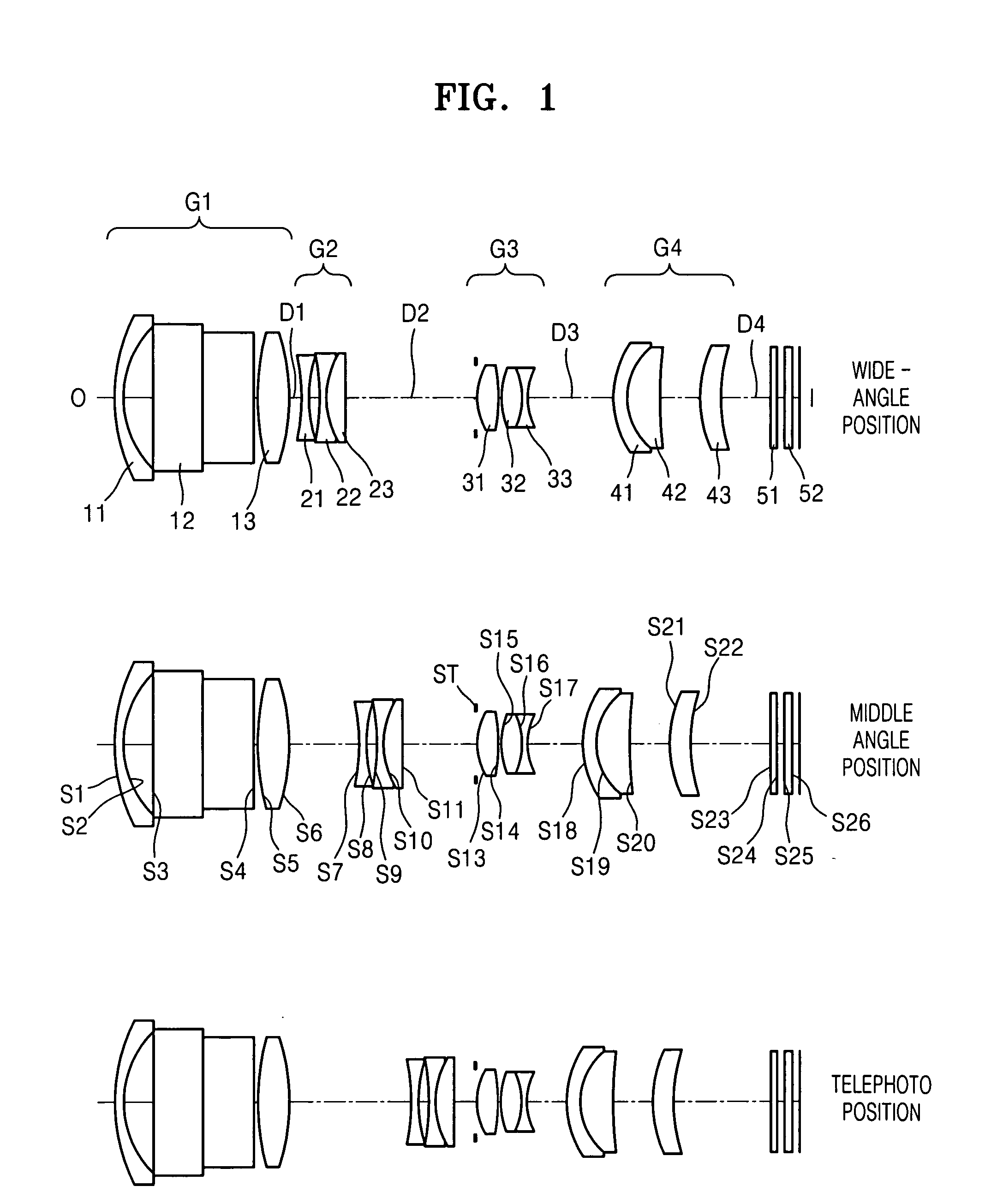
[0038]FIG. 1 is a cross-sectional view illustrating the zoom lens at a wide-angle position, a middle angle position and a telephoto position, according to an embodiment of the present invention, and reference numerals 51 and 52 denote filters.
f; 6.8 mm~11.58 mm~30.64 mm2ω; 60.6°~36.0°~21.5°RDnndvdOBJ:INFINITYINFINITYS1:15.434000.601.9228620.88S2:8.077002.16S3:INFINITY7.601.8340037.34S4:INFINITY0.30*S5:19.660202.291.7433049.33*S6:−17.70944D1S7:−27.604000.601.8061040.73*S8:10.608000.77S9:−14.519000.501.6229958.12S10:7.524001.501.8466623.78S11:78.61400D2S12(ST):INFINITY0.30*S13:6.407571.521.8061040.73S14:−34.596000.29S15:9.516001.431.6584450.84S16:−8.281000.511.9036631.3S17:4.96900D3S18:7.171001.001.9228620.88S19:5.018002.471.5168064.20S20:56.074002.98*S21:7.954111.651.5168064.20S22:13.75700D4S23:INFINITY0.501.5168064.20S24:INFINITY0.50S25:INFINITY0.501.5168064.20S26:INFINITY
[0039]Table 1 shows variable distances D1, D2, D3 and D4 at a wide-angle position, a middle angle position and a...
embodiment 2
[0042]FIG. 5 is a cross-sectional view illustrating the zoom lens at a wide-angle position, a middle angle position and a telephoto position, according to another embodiment of the present invention. The zoom lens includes first, second, third and fourth lens groups G1, G2, G3 and G4.
f; 6.8 mm~11.58 mm~30.64 mm2ω; 60.6°~36.0°~21.5°RDnndvdOBJ:INFINITYINFINITYS1:17.980000.6001.9228620.88S2:8.491002.179S3:INFINITY7.6001.8340037.34S4:INFINITY0.300*S5:17.931692.3001.7396849.00*S6:−19.28619D1S7:−81.109000.6001.7680249.24*S8:9.398001.034S9:−10.382000.5001.6229958.12S10:9.224001.5001.8466623.78S11:362.69100D2S12(ST)INFINITY0.300*S13:6.653071.5001.8047040.90S14:−32.688480.458S15:8.494001.4401.6229958.12S16:−8.494000.5001.9036631.32S17:5.10500D3S18:6.802001.0001.9228620.88S19:5.044002.4801.4874970.44S20:289.722000.359*S21:16.947581.6501.5168064.20S22:26.78800D4S23:INFINITY0.5001.5168064.20S24:INFINITY0.500S25:INFINITY0.5001.5168064.20S26:INFINITY
[0043]Table 3 shows variable distances D1, D2, ...
embodiment 3
[0046]FIG. 9 is a cross-sectional view illustrating the cases of a zoom lens at a wide-angle position, a middle angle position and a telephoto position, according to another embodiment of the present invention.
f; 6.9 mm~10.35 mm~19.67 mm2ω; 60.6°~36.0°~21.5°RDnndvdOBJ:INFINITYINFINITYS1:16.744870.6201.9228620.88S2:8.327222.220S3:INFINITY7.5001.8340037.34S4:INFINITY0.300*S5:18.692812.2801.7433049.33*S6:−19.16466D1S7:−30.879770.6001.7680249.24*S8:10.006730.895S9:−14.838170.5001.6228056.91S10:7.462531.5001.8466623.78S11:55.41687D2S12(ST):INFINITY0.300*S13:6.540461.5001.8061040.73S14:−35.609710.540S15:8.179341.4801.6400060.20S16:−6.625010.5001.9036631.32S17:5.07519D3S18:7.196060.6901.8466623.78S19:5.294542.6971.5168064.20S20:−54.503140.150*S21:20.749802.0341.5311355.70(Plastic ASP Lens)S22:22.56161D4S23:INFINITY0.5001.5168064.20S24:INFINITY0.500S25:INFINITY0.5001.5168064.20S26:INFINITY
[0047]Table 5 shows variable distances D1, D2, D3 and D4 at a wide-angle position, a middle angle posit...
PUM
 Abstract
Description
Claims
Application Information
 - R&D Engineer
- R&D Manager
- IP Professional
- Industry Leading Data Capabilities
- Powerful AI technology
- Patent DNA Extraction
Browse by: Latest US Patents, China's latest patents, Technical Efficacy Thesaurus, Application Domain, Technology Topic, Popular Technical Reports.
© 2024 PatSnap. All rights reserved.Legal|Privacy policy|Modern Slavery Act Transparency Statement|Sitemap|About US| Contact US: help@patsnap.com