

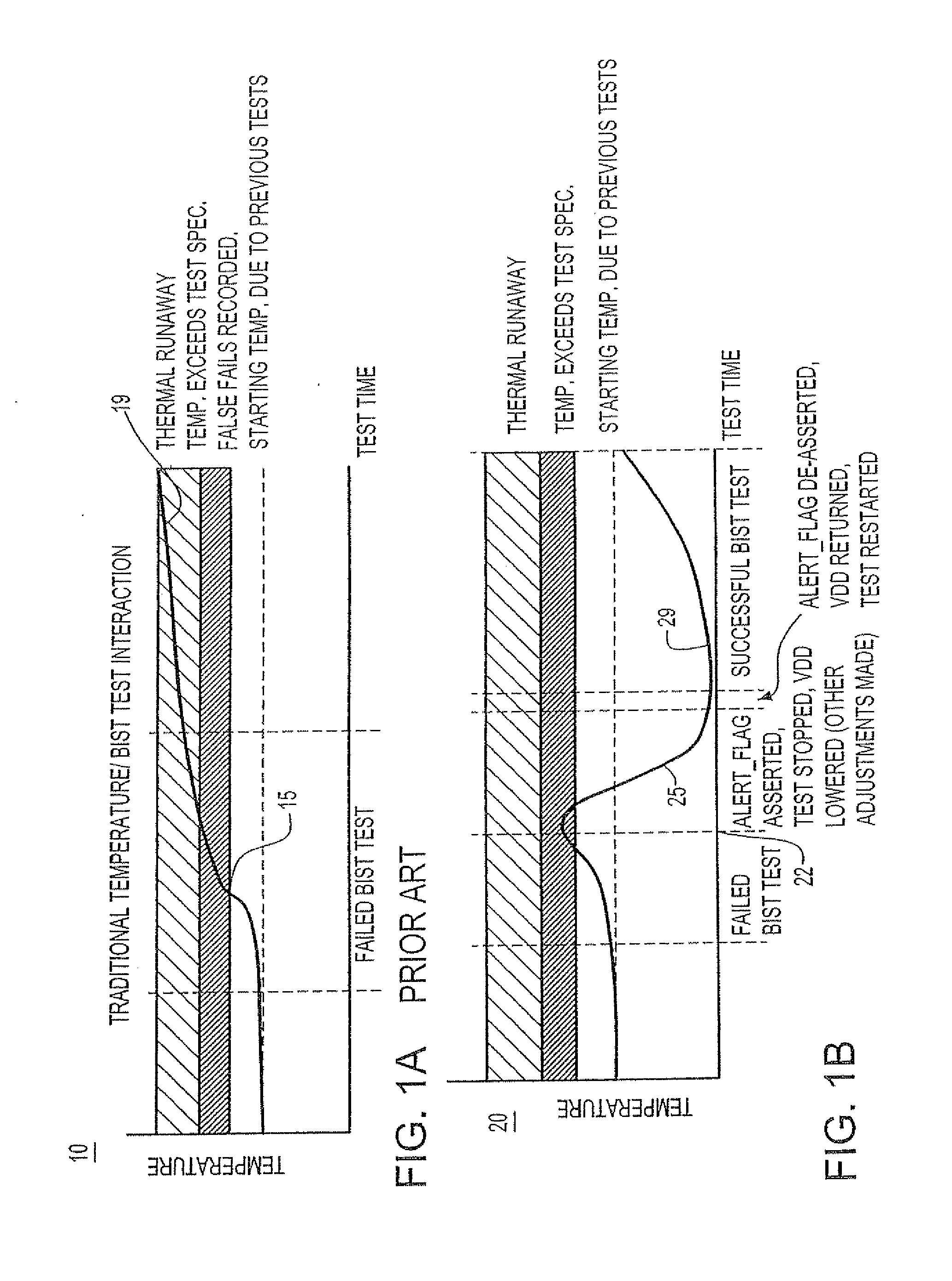
Automatic shutdown or throttling of a bist state machine using thermal feedback
a bist state machine and automatic shutdown technology, applied in the field of bist state machine automatic shutdown or throttle of bist state machine, can solve the problems of increasing the gap between how a chip is being used functionally and how it is being tested, increasing the risk of temperature limits being reached or exceeded, and increasing the risk of temperature limits
- Summary
- Abstract
- Description
- Claims
- Application Information
AI Technical Summary
Benefits of technology
Problems solved by technology
Method used
Image

Examples
first embodiment
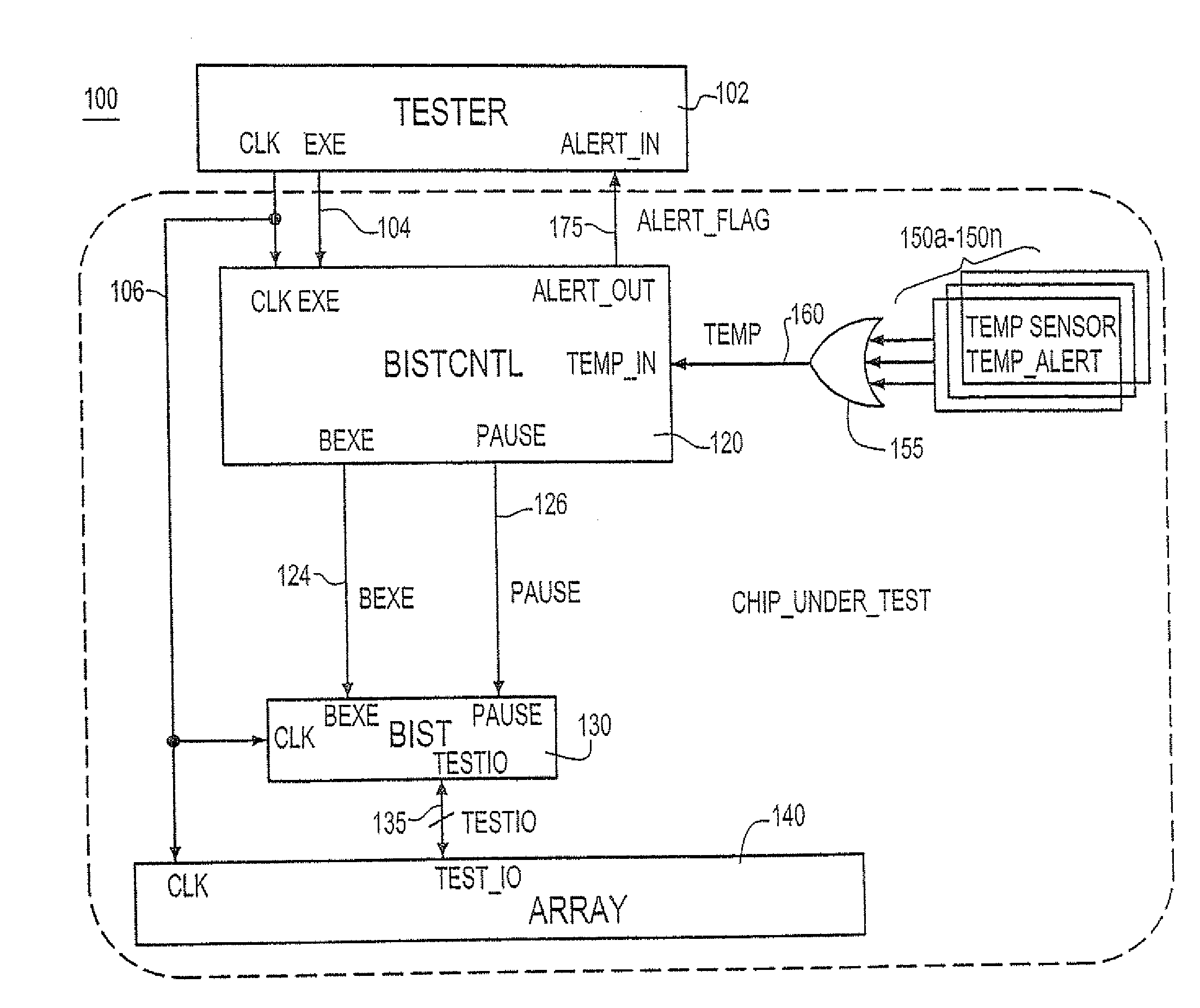
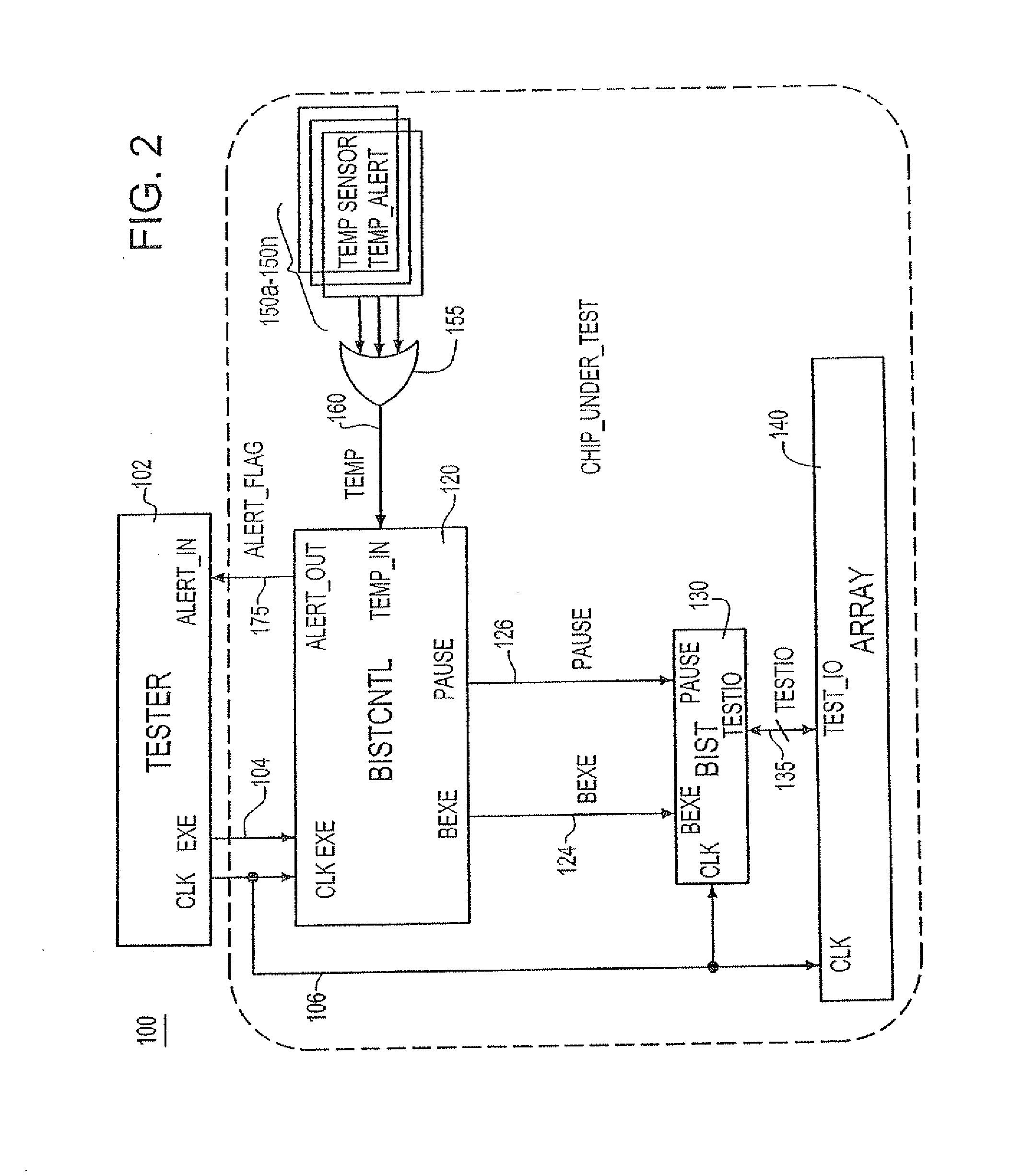
[0029]FIG. 3A depicts a BIST test methodology 200 according to the invention where test results of suspect circuits (e.g., memories) are ignored. As shown in FIG. 3A, the BIST test array executes at 205 until a TEMP signal 160 is asserted at 207 in response to the logic applied at the outputs of the one or more on-chip thermal sensor devices 150a, . . . , 150n. Upon receipt of the TEMP signal by BIST / CNTL circuit 120 (FIG. 2), the process proceeds to step 209 which represent the step of BIST / CNTL circuit 120 asserting the ALERT_FLAG 175 to the tester device and further asserting a PAUSE signal 126 to the BIST. In response to receipt of the PAUSE signal 126, BIST testing ceases collecting BIST test results as indicated at 212 until the BIST sub-pattern currently being executed completes as indicated at step 215. At such time, the BIST suspends all operations as indicated at step 219 and the tester device 102 lowers the chip under test's operating power source voltage VDD as indicated...
second embodiment
[0033]FIG. 4A depicts a BIST test methodology 300 according to the invention wherein the testing of suspect circuits (e.g., suspect memories) is temporarily stopped. As shown in FIG. 4A, the BIST test array executes at 305 until a TEMP signal 160 is asserted at 307 in response to the logic applied at the outputs of the one or more on-chip thermal sensor devices 150a, . . . , 150n. Upon receipt of the TEMP signal by BIST / CNTL circuit 120 (FIG. 2), the process proceeds to step 309 which represent the step of BIST / CNTL circuit 120 asserting the ALERT_FLAG 175 to the tester device and further asserting a PAUSE signal 126 to the BIST. In response to receipt of the PAUSE signal 126, the BIST stops testing the array as indicated at step 312 and returns to the sub-pattern at the initial (start) state at 315.
[0034]After returning to the sub-pattern at the initial (start) state at 315, the BIST suspends all operations as indicated at step 319 and the tester device 102 lowers the chip under te...
PUM
 Abstract
Description
Claims
Application Information