Bearing arrangement for veneer dryer

a technology of bearings and dryers, which is applied in the direction of bearing unit rigid support, drying machines with progressive movements, lighting and heating apparatus, etc., can solve the problems of affecting the efficiency of the drying machine, so as to achieve the effect of simple and fast replacement of bearings, significant savings in labor, downtime and parts costs

Inactive Publication Date: 2009-06-25
CROOKS WAYNE
View PDF3 Cites 6 Cited by
  • Summary
  • Abstract
  • Description
  • Claims
  • Application Information

AI Technical Summary

Benefits of technology

[0004]The invention provides a bearing mounting system particularly suited for a veneer dryer style conveyor that enables worn roller shaft bearings to be removed and replaced with significant savings in labor, downtime, and parts costs. The bearing mount permits the bearings to be changed without requiring drive sprockets to be removed. This feature saves the time otherwise needed to loosen, remove and later reposition and tighten the sprockets or risking destruction of the sprockets in an effort to remove them. The system, in the illustrated embodiment, utilizes a bearing segment of 180 degrees or less, thereby enabling it to be removed and installed on a roller shaft radially rather than sliding it axially over the normal operating location of the temporarily removed sprocket.
[0005]More specifically, the system includes a bearing mount assembly comprising a base and a holder. The base has a receiving zone with surfaces arranged to complement the configuration of the holder so as to allow the holder to self-align itself to the base. The bearing mount base is arranged to be bolted on a conventional cage angle and, as is conventional, has provisions for holding the shaft of the upper roller of the roller set. The base receives the holder, in which the bearing is disposed, radially from the space below the shaft. Extraneous assembly motion or gyration of the bearing holder is avoided and in an essentially intuitive manner, a technician can simply raise the bearing holder after roughly locating it under the lower roller shaft while biasing it against the mount base to properly position it in the receiving zone.
[0006]In addition to affording a much simpler and quicker manner of replacing the spent bearings than has been heretofore available, the invention can reduce the cost of the bearings themselves since the volume of bearing material is cut at least in half when practicing the invention compared to full cylinder prior art bearings. The bearing holder, besides serving the primary function of carrying the radial forces on the bearing, automatically captures the bearing with the base to angularly and axially lock it in place without separate retaining elements.

Problems solved by technology

The bearings, due to their operating conditions and being impractical to lubricate require relatively frequent replacement, typically as often as once a year.
The labor involved in replacing the bearings in existing prior art equipment is extensive.
Oftentimes the sprockets, which are typically keyed and closely fitted to their shafts, will be frozen on the shafts and not easily removed.
A percentage of conventional sprockets, because of corrosion, can be frozen on the shafts so tightly that it is necessary to destroy them to remove them from the shafts.
This frequent loss of sprockets obviously adds to the operating costs of the dryer.

Method used


Image

  • Bearing arrangement for veneer dryer
  • Bearing arrangement for veneer dryer
  • Bearing arrangement for veneer dryer

Examples


Embodiment Construction

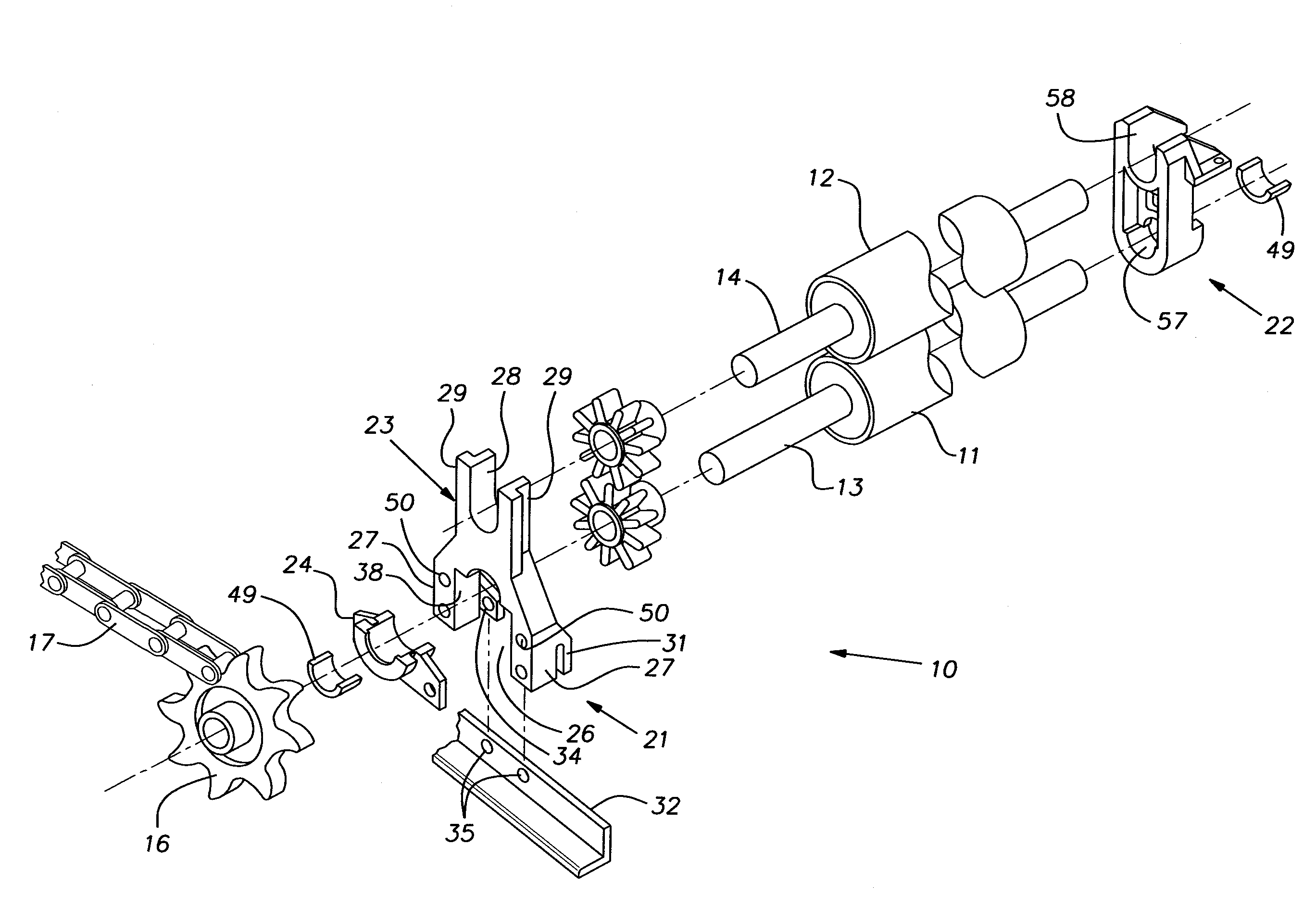
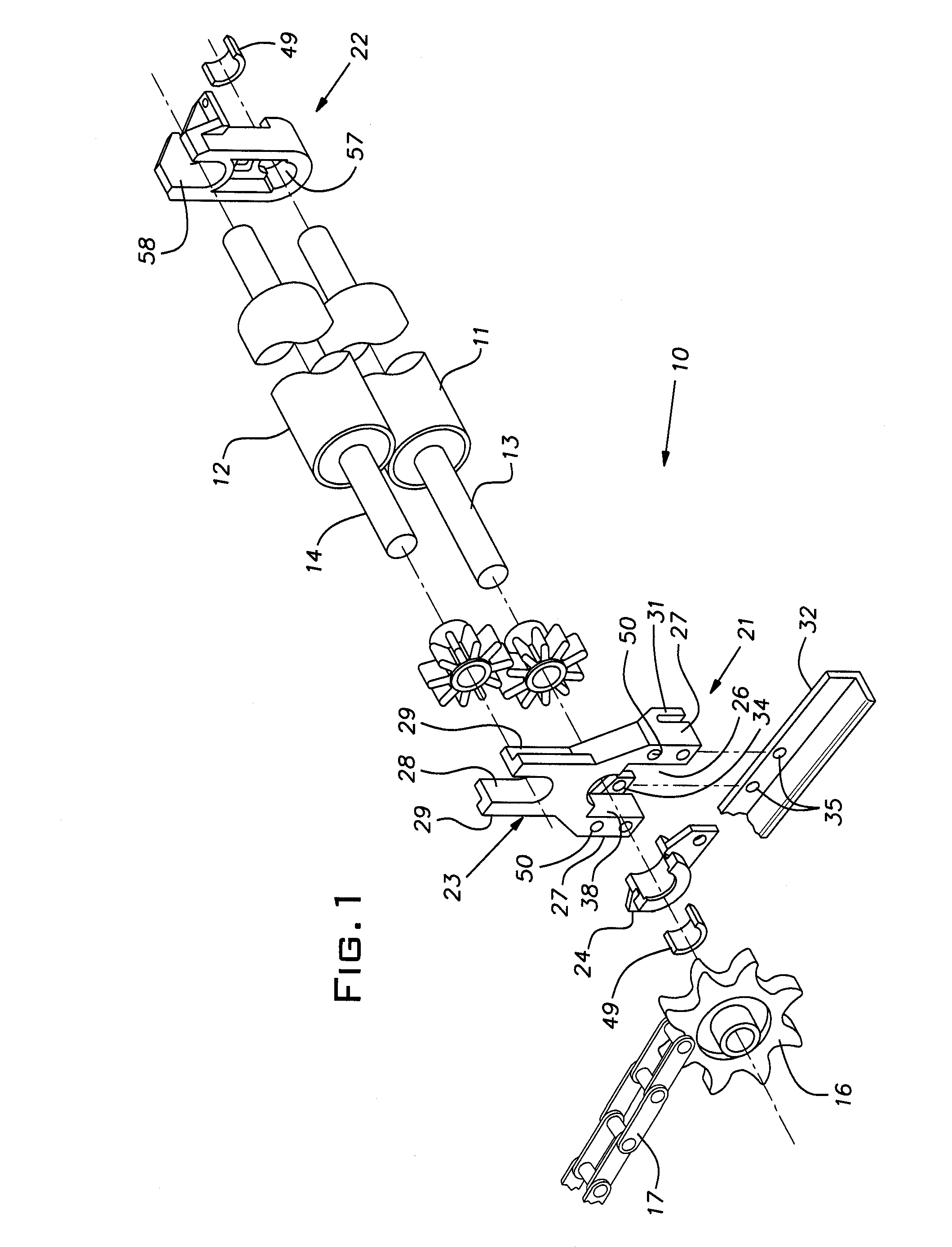
[0014]Referring now to the figures and, in particular, to FIG. 1, there is partially shown a powered roller conveyor 10 such as in a veneer dryer. The axes of pairs of rollers 11, 12 are horizontal and aligned in a common imaginary vertical plane. While only one set of rollers 11, 12 is illustrated, the conveyor 10, as is conventional, has a series of identical roller sets or pairs evenly spaced along a conveying direction in a common horizontal plane, commonly referred to as a deck. The typical dryer will have several such decks spaced one above the other. Hot air is forced through the decks to dry material being conveyed between each pair of rollers 11, 12.

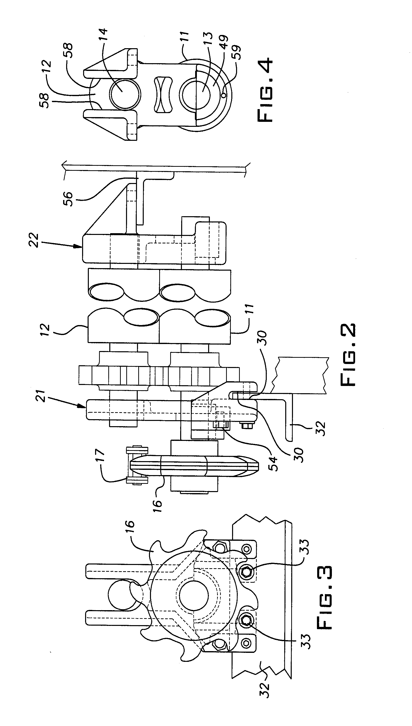
[0015]The rollers 11, 12 are carried on respective shafts 13, 14 projecting from both ends of the rollers. The lower roller shaft 11 has a sprocket 16 fixed by a key and set screw on one of its ends. The sprocket 16 and like sprockets on the other rollers of the same deck are all aligned with a common imaginary vertical plane ex...


PUM


Abstract

A bearing mount assembly for a powered roller conveyor of the type used in veneer dryers comprising a bearing mount base and a bearing holder, the base having a lower part with a vertical surface adapted to abut a cage angle and apertures for fastening it to a vertical face of the cage angle, an upper end of the base being in the shape of a yoke open at the top for locating the shaft of an upper roller, the bearing holder having a pocket for holding an arcuate section of a sleeve bearing, the base and holder having mating surfaces capable of locating the holder in a position where it supports the bearing in registry with the desired axis of rotation of the shaft of a lower roller.

Description

[0001]The invention relates to powered roller conveyors and, in particular, to improvements in bearing supports for conveyor rollers in board dryers.BACKGROUND OF THE INVENTION[0002]Dryers used in manufacturing boards and panels such as veneer dryers employ roller conveyors to carry raw material through the dryer while it is exposed to forced hot air. In a veneer dryer, for example, the powered rollers carrying the material being dried are paired, one overlying the other so as to create a nip through which the material is conveyed. In conventional designs of veneer dryers and similar equipment, the rollers, shafts, bearings and sprockets are located in confined spaces. Sprocket driven roller shafts are ordinarily carried in carbon bearings and these bearings are in-board of the sprockets and roller chain.[0003]The bearings, due to their operating conditions and being impractical to lubricate require relatively frequent replacement, typically as often as once a year. The labor involv...

Claims


Application Information

Patent Timeline
Patent Type & Authority Applications(United States)
IPC IPC(8): F16C35/06
CPCB65G39/12F16C13/02F26B2210/14F26B13/14F16C35/02
Inventor CROOKS, WAYNE
Owner CROOKS WAYNE
Why Eureka
Try Eureka