
Film deposition

Inactive Publication Date: 2005-12-08
AVIZA TECHNOLOGY INC
View PDF7 Cites 2 Cited by
  • Summary
  • Abstract
  • Description
  • Claims
  • Application Information

AI Technical Summary

Benefits of technology

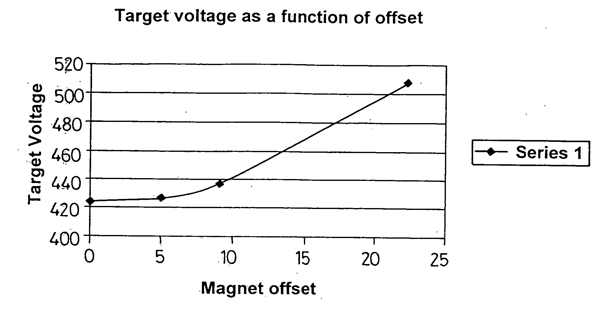
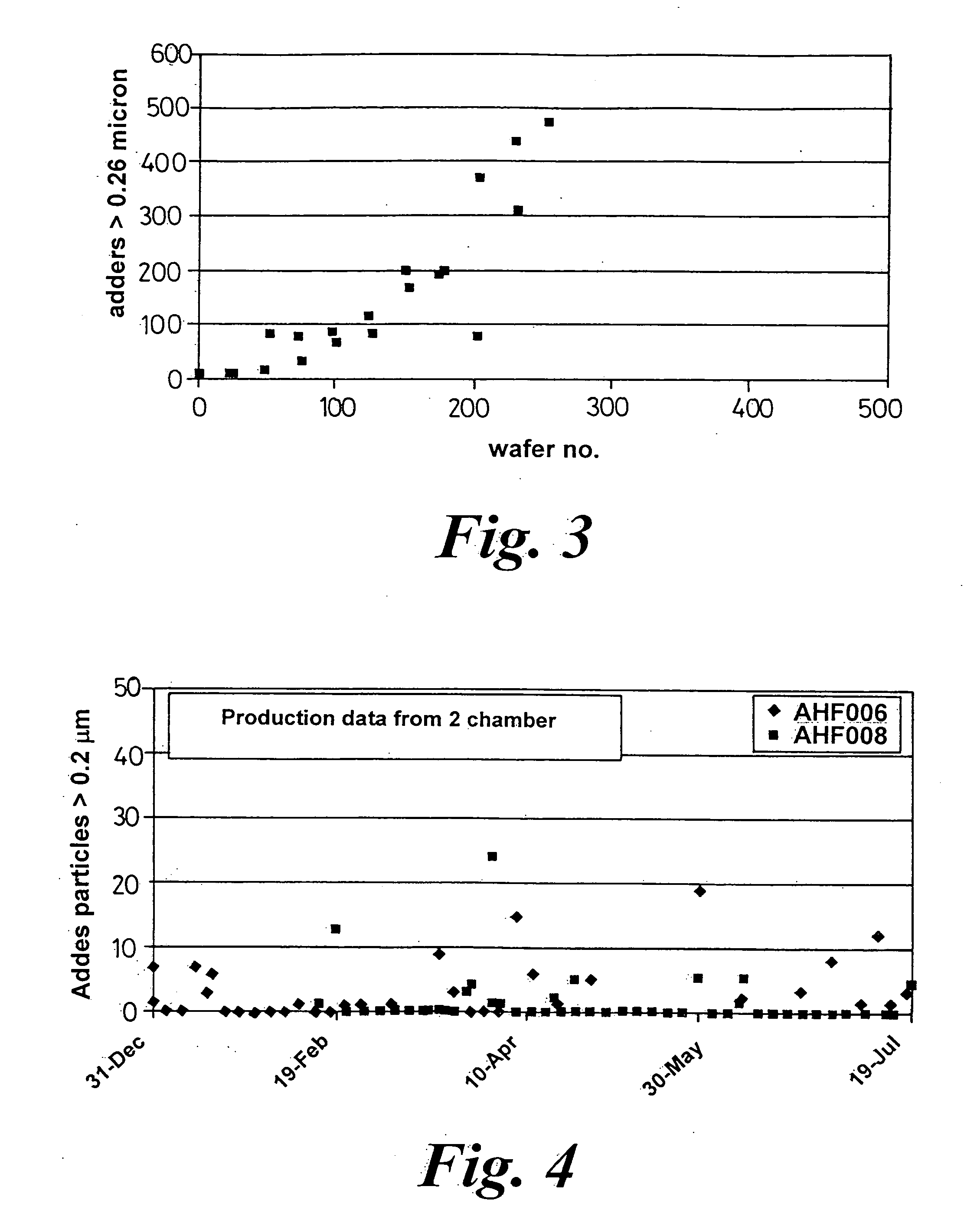
[0012] The first offset position, is selected in order to minimise electron loss between the anode used to create the plasma and the chamber wall. It has been found that this means you need a magnetron arrangement that does not erode from the very edge of the target. However, with such a target / magnetron combination it has been discovered that problems arise particularly for reactive sputtering, because the target does not have a full face erosion and can become a particle source. This is due to deposition material re-depositing on the non-eroded region of the target. Where the material is the same as the target material (i.e. non-reactive deposition) the adhesion is generally quite good, but where, as in reactive sputtering, different material is deposited and this can readily delaminate, particularly due to the extremes and rapidity of the temperature cycling which occurs as the target bias is turned on or off.
[0014] By utilising the different offset positions for the reactive and non-reactive sputtering, the Applicants have managed to overcome this problem and enabled the two processes to be performed sequentially in a single chamber, which results in significant savings both in processing time and capital cost.
[0015] The outer offset deposition position is selected to limit or prevent build up of the second film material on an outer peripheral part of the target. This position may be adjusted in accordance with target usage. The Applicants have determined that in general it is desirable to move the offset position outwardly from the axis as the target becomes more eroded.

Problems solved by technology

However, with such a target / magnetron combination it has been discovered that problems arise particularly for reactive sputtering, because the target does not have a full face erosion and can become a particle source.

Method used


Image

  • Film deposition
  • Film deposition
  • Film deposition

Examples


Embodiment Construction

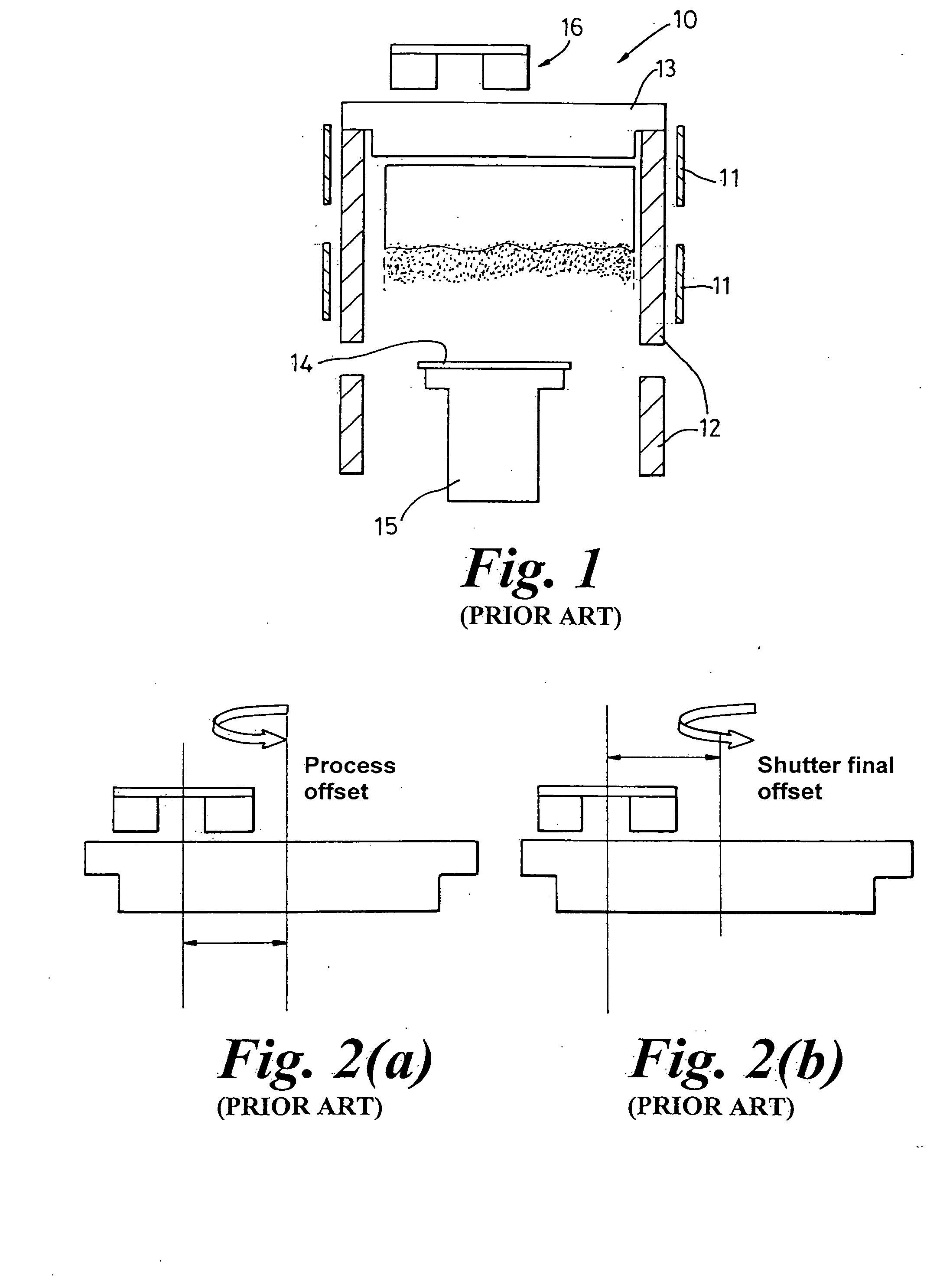
[0026] Thus in the standard Trikon Advanced Hi-Fill® AHF chamber, illustrated in FIG. 1 and generally indicated at 10, DC coils 11 extend down the chamber sidewalls 12 to allow the plasma to extend and fill a large volume of the chamber 10. This in turn increases the probability of the material leaving the target 13 becoming ionised before it reaches a wafer 14 located on a support 15. In order for this system to work correctly it is necessary to minimize any electron loss to the anode ring (not shown) and chamber walls 12. This can be achieved if the magnetron arrangement 16 is positioned so that the target material does not erode from the very edge of the target 13.

[0027] However, if one uses such a target 13 arrangement for reactive sputtering, because there is not full face erosion, the target 13 can become a particle source. As has been mentioned earlier the adhesion of the different material created in reactive sputtering can readily delaminate from the edge of the target and...


PUM


Abstract

Films are deposited on a substrate using a plasma chamber having a target disposed about an axis and a magnetron rotatable about the axis at an adjustable offset from the axis to vary the pattern of ions impinging on the target. In the deposition of the films, a first film of target material is deposited with the magnetron at a first inner-offset position relative to the axis, and in the same chamber, a second film is deposited using a reactive physical vapour deposition process with the magnetron at a second outer offset position. The deposition of the first and second film can occur in any order.

Description

CROSS REFERENCED TO RELATED APPLICATION [0001] A claim to priority is made to U.S. Provisional Application Ser. No. 60 / 582,536, filed Jun. 25th 2004 and to British Patent Application No. 0412469.9, filed Jun. 4th 2004.BACKGROUND OF THE INVENTION [0002] 1. Field of the Invention [0003] This invention relates to methods of depositing films on the substrate using a plasma chamber having a target disposed about an axis and a magnetron rotatable about the axis at an adjustable offset from the axis. [0004] 2. Description of the Related Art [0005] The use of magnetrons in sputtering processes is well known and the are provided for the purposes of controlling the erosion of the target. Examples of prior art systems are shown in WO-A-02 / 47110 wherein adjustment of the offset position of the magnetic assembly of the magnetron in accordance with a process characteristic is known and EP-A-1094495 in which a magnetron can take up two distinct rotation diameters, the first being used in depositio...

Claims


Application Information

Patent Timeline
IPC IPC(8): C23C14/00C23C14/06C23C14/16C23C14/32C23C14/35
CPCC23C14/0036C23C14/35C23C14/165C23C14/0641
Inventor BURGESS, STEPHEN ROBERTRICH, PAULO'SULLIVAN, JAMES
Owner AVIZA TECHNOLOGY INC
Learn More