
Carbon Dioxide Separation Via Partial Pressure Swing Cyclic Chemical Reaction

a cyclic chemical reaction and carbon dioxide technology, applied in the direction of hydrogen separation using solid contact, metal/metal-oxide/metal-hydroxide catalyst, chemical production, etc., can solve the problems of significant heat exchange capital expenditure and unavoidable energy loss, and the description of the high temperature and high temperature separation process of ambient temperature and high temperature,

Inactive Publication Date: 2009-06-25
AIR PROD & CHEM INC
View PDF7 Cites 45 Cited by
  • Summary
  • Abstract
  • Description
  • Claims
  • Application Information

AI Technical Summary

Benefits of technology

[0020]It is advantageous that at least 15 kcal / gmole of the reactive gas component be released during the reacting of the feed gas mixture with the reactive solid in the exothermic chemical reaction.

Problems solved by technology

There are however, disadvantages associated with both the ambient temperature and high temperature separation processes described above.
The ambient temperature processes require substantial cooling of the syngas to achieve the typical 40-70° C. operating temperatures, which translates into significant heat exchange capital expenditure and unavoidable energy losses.
Steam used in the process is condensed during the syngas cooling, so the steam is not available for downstream turbine flow and power generation.
The cool product gas resulting from the process is not efficiently combusted in a gas turbine, so typically it is reheated to between about 300-400° C., again requiring heat exchange capital expenditure and energy losses.
The processes are limited, though, by the relatively low CO2 adsorption capacities associated with the high temperature adsorbent materials.
The low adsorption capacities require relatively large beds which can be expensive to construct.
Thermal regeneration of the reactive solids is challenging, though, since they generally require temperatures in excess of 800° C. Such high regeneration temperatures entail significant energy costs, reducing the efficiency of the process.
These high temperature conditions can be difficult to generate and maintain within the vessels.
Vessel design / integrity is also a significant issue.

Method used


Image

  • Carbon Dioxide Separation Via Partial Pressure Swing Cyclic Chemical Reaction
  • Carbon Dioxide Separation Via Partial Pressure Swing Cyclic Chemical Reaction
  • Carbon Dioxide Separation Via Partial Pressure Swing Cyclic Chemical Reaction

Examples


Embodiment Construction

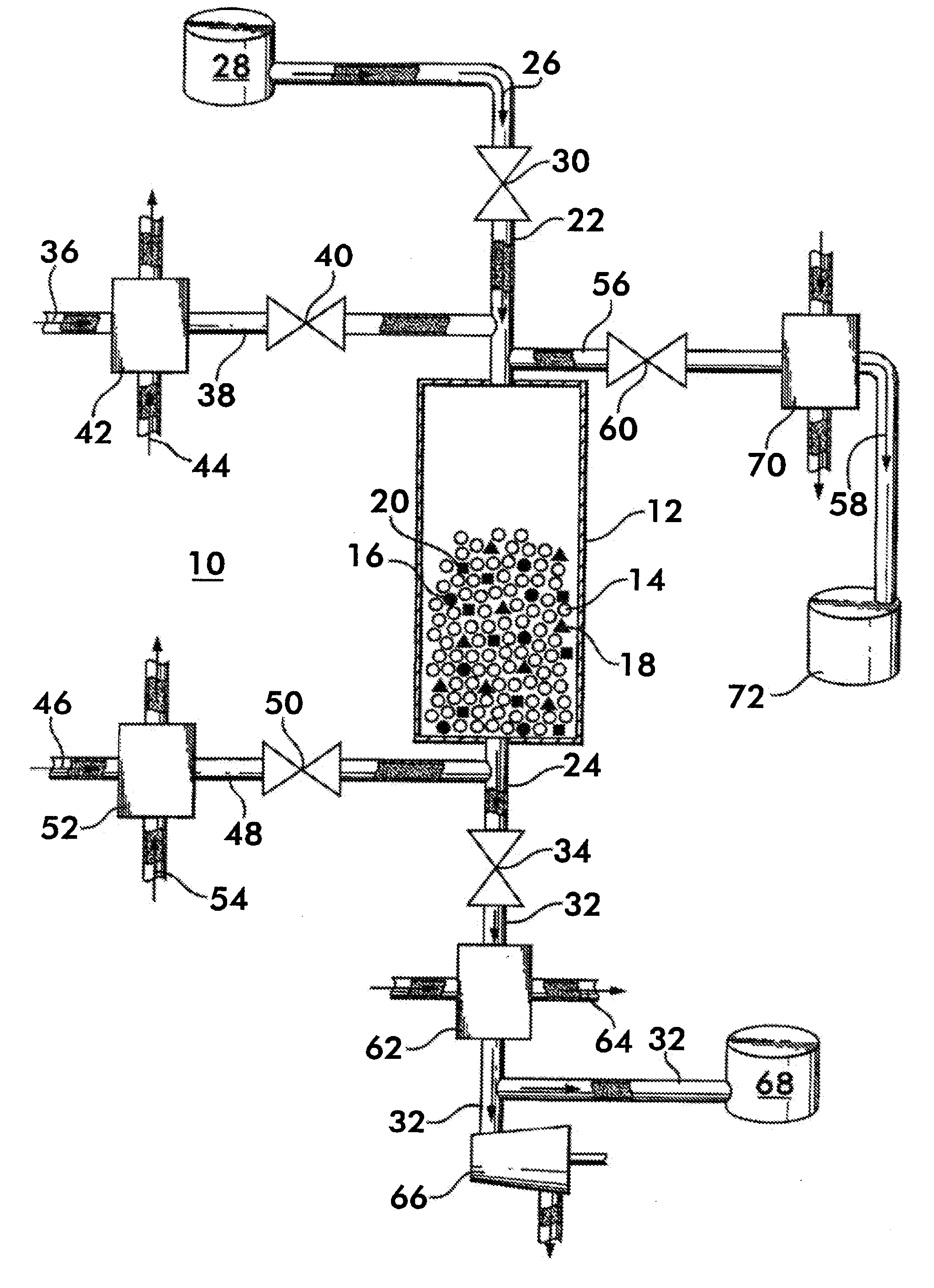
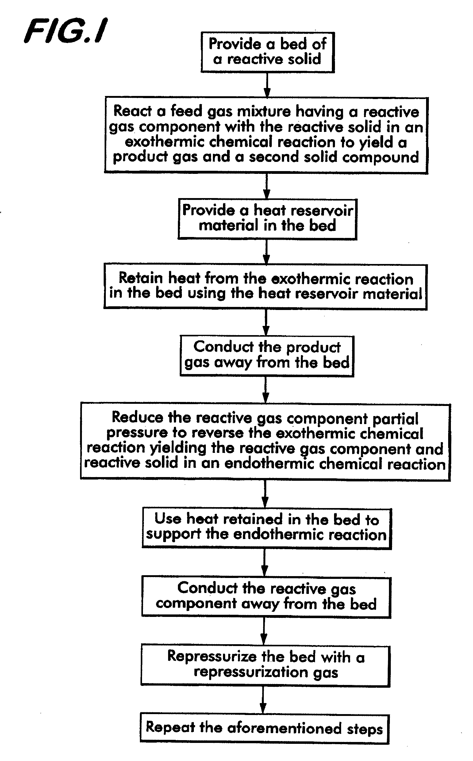
[0041]The method of separating CO2 from a syngas according to the invention uses a bed of high temperature reactive solids, defined herein as solids that can react with CO2 in the temperature range of 400° C.-800° C. with a heat of reaction greater than 15 kcal / gmole of CO2. By bed is meant a grouping of solid matter which provides a surface area which can contact a gas or other fluid to facilitate a chemical or physical reaction between the solid matter and the gas. Known approaches for using these types of materials utilize thermal regeneration at temperatures of 800° C. and above. The method according to the invention utilizes these materials in a process cycle which includes a regeneration step where the partial pressure of CO2 in the bed is reduced to a level below the feed gas mixture. This can be accomplished by either reducing the total gas pressure or reducing the CO2 concentration. Another key aspect of the invention relates to heat retention in the bed—the heat of reactio...


PUM

PropertyMeasurementUnit
temperatureaaaaaaaaaa
partial pressureaaaaaaaaaa

Abstract

A method for separating a reactive gas from a feed gas mixture is disclosed. The method includes reacting the reactive gas with a bed of reactive solid in an exothermic reaction to create a second solid and a product gas from which the reactive gas is depleted. The product gas is removed and the heat from the reaction is used to liberate the reactive gas from the second solid in an endothermic reaction which yields the reactive solid. The reactive gas is removed and sequestered. Heat reservoir material is included in the bed to retain the heat in support of the endothermic reaction. A device for executing the method having an insulated chamber holding the bed, as well as process units formed of multiple beds are also disclosed. The process units allow the method to be operated cyclically, providing a continuous flow of feed gas, reactive gas and product gas.

Description

STATEMENT REGARDING FEDERALLY SPONSORED RESEARCH OR DEVELOPMENT[0001]This invention was made with Government support under DOE Agreement No. DE-FC26-01 NT41145 awarded by DOE. The Government has certain rights in this invention.BACKGROUND OF THE INVENTION[0002]This invention concerns a method and a device for separating reactive gases, such as carbon dioxide, from a feed gas mixture, using partial pressure swing cyclic chemical reaction techniques.[0003]To avoid the discharge of CO2 to the environment during power generation, it is economically advantageous to remove the carbon as CO2 from fuels such as coal, oil, natural gas, biogas and other gaseous hydrocarbon compounds before the fuel is burned. Removal of the carbon is accomplished by first generating a so-called “syngas” from the fuel using various techniques such as steam reforming, partial oxidation and gasification as appropriate for the particular fuel. The syngas may be comprised of hydrogen, steam, CO2 and CO as well as ...

Claims


Application Information

Patent Timeline
Patent Type & Authority Applications(United States)
IPC IPC(8): B01D53/62B01D53/38B01J8/18C01B32/50
CPCB01D53/0462Y02C10/08B01D53/62B01D53/96B01D2251/30B01D2251/40B01D2256/16B01D2257/504B01D2259/4002B01D2259/40043B01D2259/40086B01D2259/4009B01D2259/655B01D2259/657B01J23/862B01J23/868C01B3/16C01B3/56C01B2203/043C01B2203/0475C01B2203/86Y02C10/04B01D53/047Y02P20/52Y02P30/00Y02C20/40Y02P20/151
Inventor HUFTON, JEFFREY RAYMONDQUINN, ROBERTWHITE, VINCENTALLAM, RODNEY JOHN
Owner AIR PROD & CHEM INC
Features
  • Generate Ideas
  • Intellectual Property
  • Life Sciences
  • Materials
  • Tech Scout
  • Unparalleled Data Quality
  • Higher Quality Content
  • 60% Fewer Hallucinations
Learn More