Heat Cycle System and Composite Heat Cycle Electric Power Generation System

a heat cycle and electric power generation system technology, applied in the direction of machines/engines, mechanical equipment, transportation and packaging, etc., can solve the problem of difficult to increase the heat crossing ratio qsub>3/sub>/q, and achieve the effect of improving the thermal efficiency of the heat cycle electric power generation system, high efficiency, and improving the thermal efficiency of the composite heat cycle system

Inactive Publication Date: 2009-07-02
MASADA NOBORU
View PDF6 Cites 65 Cited by
  • Summary
  • Abstract
  • Description
  • Claims
  • Application Information

AI Technical Summary

Benefits of technology

[0037]An object of the present invention is to provide a high-efficiency heat cycle system including a compressor, an expander, and first and second heat exchangers and a composite heat cycle electric power generation system using the system. Another object of the present invention is to provide a heat cycle system that is capable of using a dissipating side of the second heat exchanger of the heat cycle system as a low-temperature chamber such as a chamber to be air-conditioned, a refrigerator, or an ice-making chamber, or a dissipating portion for waste heat of various types. Another object of the present invention is to provide a high-efficiency heat cycle system adapted to transfer waste heat or heat in nature to working fluid and use the heat. Another object of the present invention is to improve the thermal efficiency of a composite heat cycle system formed by combining a steam turbine and a refrigerator. Another object of the present invention is to improve the thermal efficiency of the heat cycle electric power generation system by transferring (heat crossing) the waste heat of steam turbine outlet steam to working fluid at the steam turbine inlet side. Another object of the present invention is to provide a heat cycle system that is capable of forming a low heat source by combining a heat receiving side (heat absorbing side) of the heat cycle system with a heat dissipating side of a refrigerating machine, the low heat source having such an extremely low temperature as to liquefy a gas such as LNG or LPG.

Problems solved by technology

It is difficult to increase the heat crossing ratio Q3 / Q in heat cycles other than the refrigerating cycle.

Method used


Image

  • Heat Cycle System and Composite Heat Cycle Electric Power Generation System
  • Heat Cycle System and Composite Heat Cycle Electric Power Generation System
  • Heat Cycle System and Composite Heat Cycle Electric Power Generation System

Examples


first embodiment

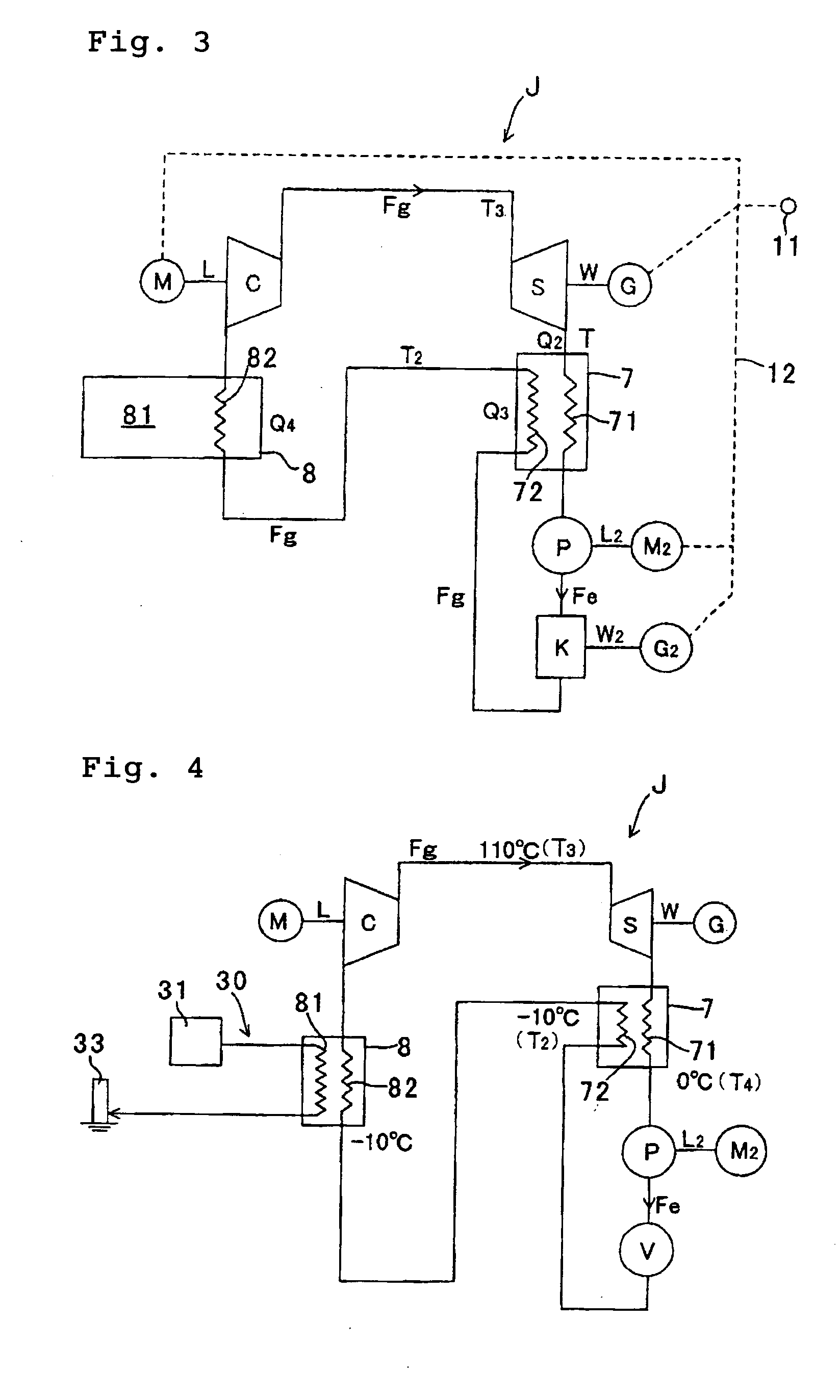
[0060]FIG. 3 is an arrangement plan of a heat cycle system J according to the present invention. The heat cycle system J has an arrangement in which a turbine S and so forth are inserted into a refrigerator including a compressor C and a condenser. Working fluid (refrigerant gas Fg) compressed in the compressor C drives the turbine S to deliver work W. Thereafter, the working fluid is cooled and liquefied in a heat dissipating side 71 of a heat exchanger 7. A pump P connected to the outlet of the heat exchanger 7 sucks in the working liquid Fe and lowers the back pressure of the turbine S, thereby increasing the turbine output W and raising the pressure of the working liquid Fe. The working liquid Fe raised in pressure drives a reaction water turbine K to deliver work W2. At the same time, the working liquid Fe is expanded by the reaction water turbine K that operates as an expansion valve. Thus, the working liquid Fe evaporates to form working gas (refrigerant gas Fg). The working ...

fourth embodiment

[0068]FIG. 6 is an arrangement plan of a composite heat cycle system according to the present invention. The composite heat cycle system of FIG. 6 comprises: a refrigerator (heat pump) J including a compressor C, first and second heat exchangers 7 and 9, and an expander V; and a steam engine A including a boiler B, a second turbine S2, condenser Y, a third power generator G3 driven by the second turbine S2, and a second pump P2. The second heat exchanger 8 comprises a condenser Y of the steam engine A. In the composite heat cycle system, the working gas Fg compressed in the compressor C is chilled as it passes the heat dissipating side 71 of the first heat exchanger 7, so as to form working liquid Fe, which is in turn expanded in the expansion valve V to form low-temperature working gas Fg, which is in turn heated as it passes the heat receiving side 82 of the condenser Y, and is thereafter introduced to the compressor C.

[0069]In the composite heat cycle system according to the four...

fifth embodiment

[0070]FIG. 7 is an arrangement plan of a composite heat cycle system according to the present invention. The composite heat cycle system of FIG. 7 comprises: a refrigerator (heat pump) J including a compressor C, a first turbine S, a first heat exchanger 7, a first pump P, a water turbine K, and a first power generator G; and a Rankine heat engine A including a boiler B, a second turbine S2, a third power generator G3, a condenser Y, and a second pump P2. Working gas Fg compressed in the compressor C is chilled as it passes the heat dissipating side 71 of the first heat exchanger 7 after driving the first turbine S, and is thereafter increased in pressure by the first pump P to form high-pressure working liquid Fe, which is expanded and evaporated in the water turbine K to form working gas Fg, which is heated as it passes the heat receiving side 72 of the first heat exchanger 7 and the heat receiving side S2 of the condenser Y, and is thereafter introduced to the compressor. After d...


PUM


Abstract

A high-efficiency heat cycle system including a compressor, a first turbine, first and second heat exchangers 7 and 8, a first pump, and an expander, and a composite heat cycle power generator using the high-efficiency heat cycle system. Working gas Fg compressed in the compressor (C) drives a first turbine (S) and is thereafter cooled by passing through a heat dissipating side of a first heat exchanger (7) and then raised in pressure by a first pump (P) to form high-pressure working liquid Fe, the high-pressure working liquid is expanded and evaporated in a expander (K) to form working gas Fg, said working gas Fg is heated by passing through a heat receiving side 82 of the second heat exchanger before being introduced into the compressor C. A heat dissipating side 81 of the second heat exchanger comprises a heat dissipating portion of a refrigerating machine or a heat dissipating portion for waste heat from a heating machine.

Description

TECHNICAL FIELD[0001]The present invention relates to a heat cycle system including a compressor, an expander, a power generator, first and second heat exchangers, and a composite heat cycle electric power generation system using the heat cycle system. More particularly, the present invention relates to a heat cycle system and a composite heat cycle electric power generation system having such a heat cycle system combined with a Rankine cycle system. In the heat cycle system, working gas compressed in a compressor is chilled and condensed as it passes a heat dissipating side of the first heat exchanger, after driving the first turbine, and is thereafter increased in pressure by a pump to form high-pressure working liquid, which is expanded and evaporated in an expander to form working gas, which is heated (heat crossing) as it passes heat receiving sides of the first and second heat exchangers, and is thereafter introduced to the compressor.BACKGROUND ART[0002]There have heretofore ...

Claims


Application Information

Patent Timeline
Patent Type & Authority Applications(United States)
IPC IPC(8): F01K27/00F01K11/00F01K17/02
CPCF01K9/003F01K17/005F01K23/10F01K25/10Y02E20/14F02C6/18Y02E20/16F05D2210/10F02C1/10
Inventor MASADA, NOBORU
Owner MASADA NOBORU
Why Eureka
Try Eureka