Cryopump and evacuation method

a technology of cryopump and evacuation method, which is applied in the direction of positive displacement liquid engine, separation process, lighting and heating apparatus, etc., can solve the problems of increased temperature of cryopanel, adverse effect of pumping performance, increase in energy consumption required to cool cryopanel sufficiently, etc., and achieve high pumping performance

Active Publication Date: 2009-07-02
SUMITOMO HEAVY IND LTD
View PDF4 Cites 19 Cited by
  • Summary
  • Abstract
  • Description
  • Claims
  • Application Information

AI Technical Summary

Benefits of technology

[0007]In this background, a general purpose of the present invention is to provide a cryop

Problems solved by technology

For this reason, energy consumption required to cool the cryopanels sufficiently will be increased.
Further

Method used


Image

  • Cryopump and evacuation method
  • Cryopump and evacuation method
  • Cryopump and evacuation method

Examples


first embodiment

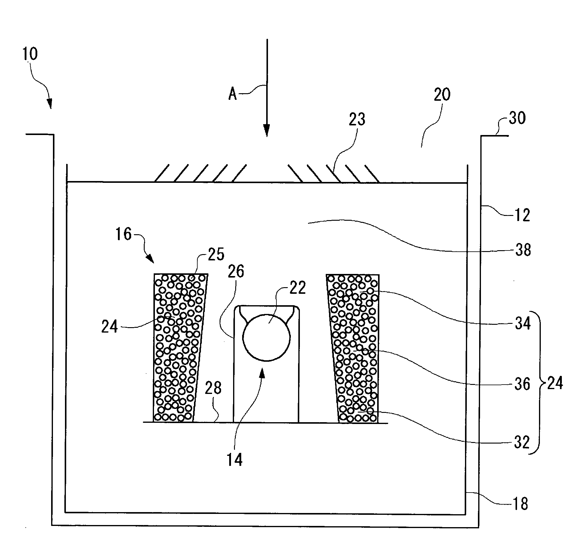
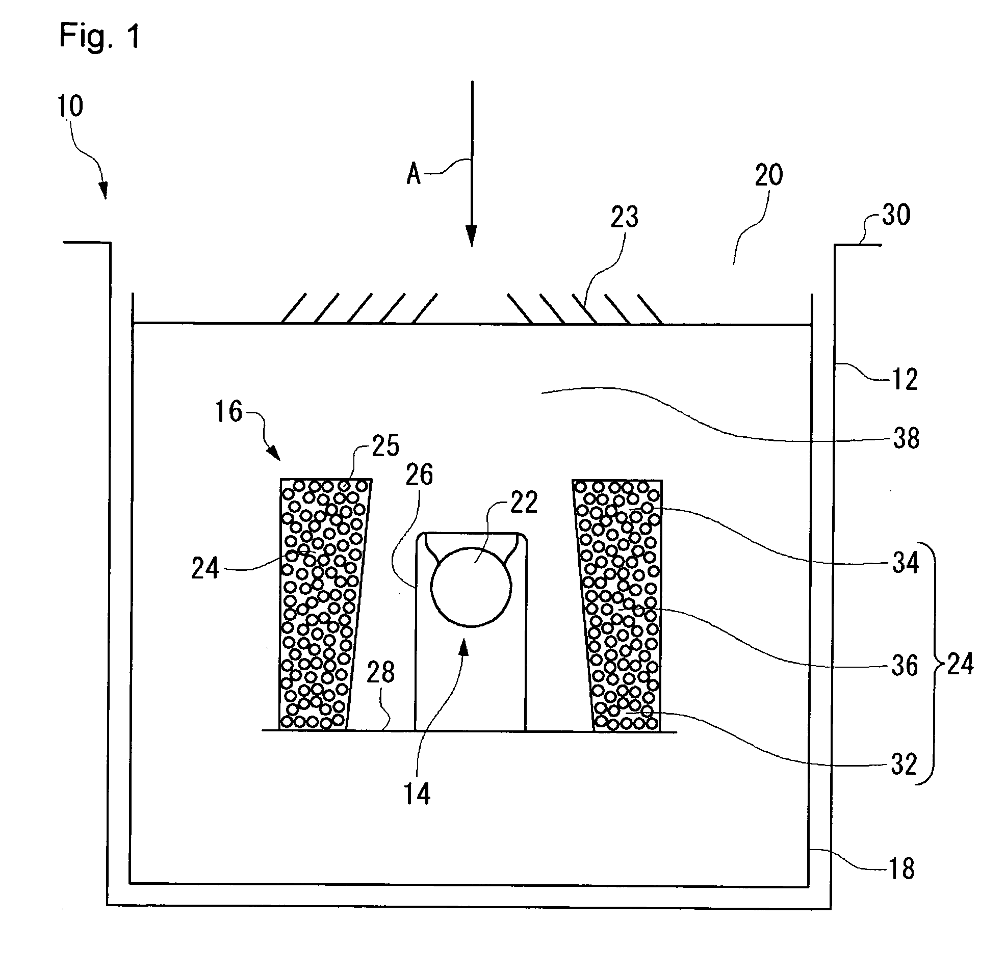
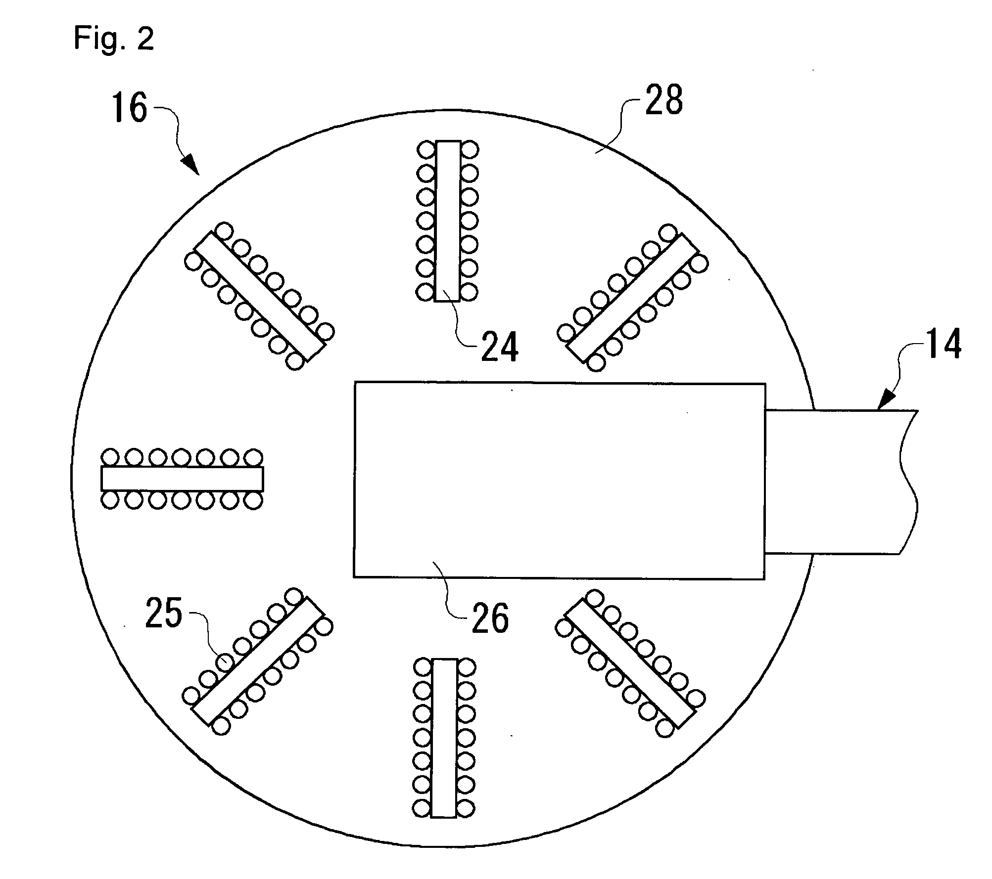
[0035]FIGS. 1 and 2 schematically show a part of a cryopump 10 according to the present invention. The cryopump 10 is mounted in a vacuum chamber of an apparatus, such as an ion implantation apparatus and a sputtering apparatus, that requires a high vacuum environment. The cryopump 10 is used to enhance the degree of vacuum in the vacuum chamber to a level required in a requested process. For example, the cryopump 10 achieves a high degree of vacuum of about 10−5 Pa or about 10−8 Pa.

[0036]The cryopump 10 comprises a pump chamber 12, a refrigerator 14, a panel structure 16, and a heat shield 18. The cryopump 10 shown in FIG. 1 is of horizontal type. Generally, a cryopump of horizontal type is configured such that a second cooling stage 22 of the refrigerator 14 is introduced into the heat shield 18 in a direction (normally, the perpendicular direction) intersecting the axial direction of the cylindrical heat shield 18.

[0037]The invention is equally applicable to a cryopump of vertica...

second embodiment

[0096]A refrigerator mounting hole 42 is formed in the side of the heat shield 18 toward the bottom of the pump. More specifically, the refrigerator mounting hole 42 is formed in the side of the heat shield 18 close to the bottom of the pump. The second stage cylinder 7 and the second cooling stage 22 of the refrigerator 14 are introduced through the refrigerator mounting hole 42 in a direction perpendicular to the direction of central axis of the heat shield 18. The heat shield 18 is thermally coupled to the first cooling stage 21 via the refrigerator mounting hole 42 and secured in that state. Thus, in the second embodiment, the second cooling stage 22 of the refrigerator 14 is provided at a position farther from the opening 20 than the center of the heat shield 18 in the direction A. Accordingly, the second cooling stage 22 is provided at a position farther from the opening 20 than the center of the pump chamber 12 in the direction A. Further, the second cooling stage 22 is provi...


PUM


Abstract

A cryopump includes: a cryopump chamber having an inlet port through which a gas to be pumped is introduced; a refrigerator provided with a second cooling stage provided in the cryopump chamber; an intermediate member thermally coupled to the second cooling stage; and a cryopanel having a connecting part connected to the intermediate member at a position farther from the inlet port in the direction in which the gas is introduced than the second cooling stage, and extending from the connecting part toward the inlet port. For example, a cryopump having a suspended panel structure is provided.

Description

BACKGROUND OF THE INVENTION[0001]1. Field of the Invention[0002]The present invention relates to a cryopump and an evacuation method.[0003]2. Description of the Related Art[0004]A cryopump is a vacuum pump that captures and pumps gas molecules by condensing or adsorbing molecules on a cryopanel cooled to an extremely low temperature. A cryopanel is generally used to achieve a clean vacuum environment required in a semiconductor circuit manufacturing process.[0005]For example, cited document 1 describes a cryopump provided with a plurality of elongated panels mounted in a radial pattern on the back of a heat shield panel with respect to the direction in which the gas is introduced and extending backward from the heat shield panel. [patent document No, 1] JP 2-308985[0006]In the aforementioned cryopump, a heat shield panel is provided close to and opposite to the opening through which the gas to be pumped is introduced. The heat shield panel restricts the flow of gas to the cryopanels...

Claims


Application Information

Patent Timeline
IPC IPC(8): F04B37/08B01D8/00
CPCF04B37/08
Inventor MATSUBARA, TAKAHIRO
Owner SUMITOMO HEAVY IND LTD
Why Eureka
Try Eureka