This helps you quickly interpret patents by identifying the three key elements:
Problems solved by technology
Method used
Benefits of technology
Benefits of technology
[0011]The present invention is made to solve the problems in the prior art, and one object of the present invention is to provide a pneumatic tire which has sufficient total property and mass productivity of a tire without reducing drainage capability due to the reduction of volume of circumferential grooves, achieves high design flexibility of tread patterns and stiffness of land portions as intended, and also effectively reduces undesired air column resonance noise produced by the circumferential grooves.
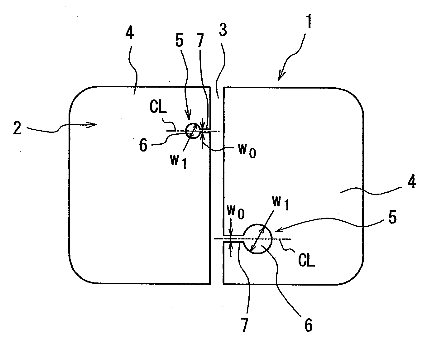
[0069]That is, with the plane maximum width of the narrowed neck of less than 3%, the neck is sealed, which makes it difficult to constantly achieve the effect of noise reduction as required without fail, while the width over 50%, the neck has too large air volume therein, which makes it difficult to obtain a sufficient amplitude of oscillation of the air at a resonance frequency, as the result of that the effect of noise reduction is decreased.
Problems solved by technology
However, in the prior art in which reduces the volume of a circumferential groove of a tire, the drainage capability of the tire is inevitably lowered.
Also in the invention described in Patent Document 1 which involves an arrangement of an elongated lateral groove, there is a problem that it is difficult to secure the design flexibility of tread patterns and appropriate stiffness of land portions.
Meanwhile, it cannot be said that each of the inventions described in Patent Document 2 to 4 discloses any specific and effective method for arranging Helmholtz-type resonators in a tread of a tire with full consideration of the reduction of the collision noise of a land portion of a tire against road surface, the whole performance of the tire such as wear resistance and anti-stone trapping property of the land portion, the mass productivity of the tire, and the like, and such a tire with an effective use of resonators has not been in an advanced stage of development yet.
Method used
Image
Click on the blue label to locate the original text in one second.
Reading with bidirectional positioning of images and text.
Examples
example 1
[0138]A tire (size: 195 / 65R15) mounted to a 6JJ rim and inflated with an air pressure of 210 kPa is rotated at a speed of 80 km / h with a load of 4.47 kN applied thereto using an indoor drum tester, and the sound on both sides of the tire is measured according to the condition specified in JASO C606 to obtain partial overall values in a 1 / 3 octave band with center frequencies of 800 Hz, 1000 Hz, and 1250 Hz.
[0139]In this case, the result of a reduction of sound pressure by 2 dB or more is determined to be effective because the amount of reduction can be expected to improve the feeling evaluation by a driver in a real car test.
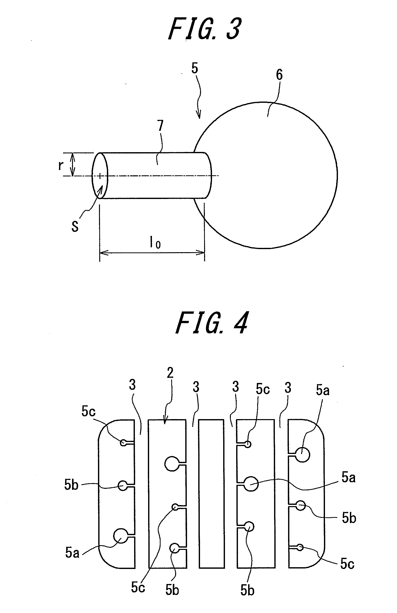
[0140]The resonator had the resonance frequency f0 obtained by the following formula as described above:
f0=c2πS(l0+1.3r)V[Formula5]
[0141]In the present example, the sound velocity c is 343.7 m / s.
[0142]The measured result with a conventional tire having a ground contact area with four straight circumferential grooves extending therein, each of the groove having a...
example 2
[0145]The difference of noise level between the Example tire having resonators which were arranged as shown in FIG. 7(b) and had different resonance frequencies f0 in each band and the above conventional tire is obtained as in the case of Example 1.
[0146]The resulting effect of noise reduction in the Example tire is shown in FIG. 8.
[0147]According to FIG. 8, with the average of the resonance frequencies f0 within a range of from 700 to 1800 Hz, a target result of reduction of air column resonance noise by 2 dB or more can be obtained, and particularly, with a range of from 700 to 1400 Hz, obviously the effect is significantly large.
example 3
[0148]The noise by the Example tire having resonators which were arranged to each circumferential groove so that three types of resonators were included in a ground contact area simultaneously at any moment, with one resonator having a fixed middle resonance frequency of about 1000 Hz and the other two resonators individually having a higher resonance frequency and a lower resonance frequency than the about 1000 Hz, and that by the above conventional tire were measured as in the case of Example 1.
[0149]The resulting noise reduction effects were organized based on the difference between the maximum value and the minimum value of the resonance frequencies in the Example tire as a parameter, which is shown in FIG. 9.
[0150]In the present example, with a desired level effect by 1 dB or more reduction as compared to that in the case where the difference between the resonance frequencies is 0 (all of three resonators have the resonance frequency of about 1000 Hz), the large effects in redu...
PUM
Abstract
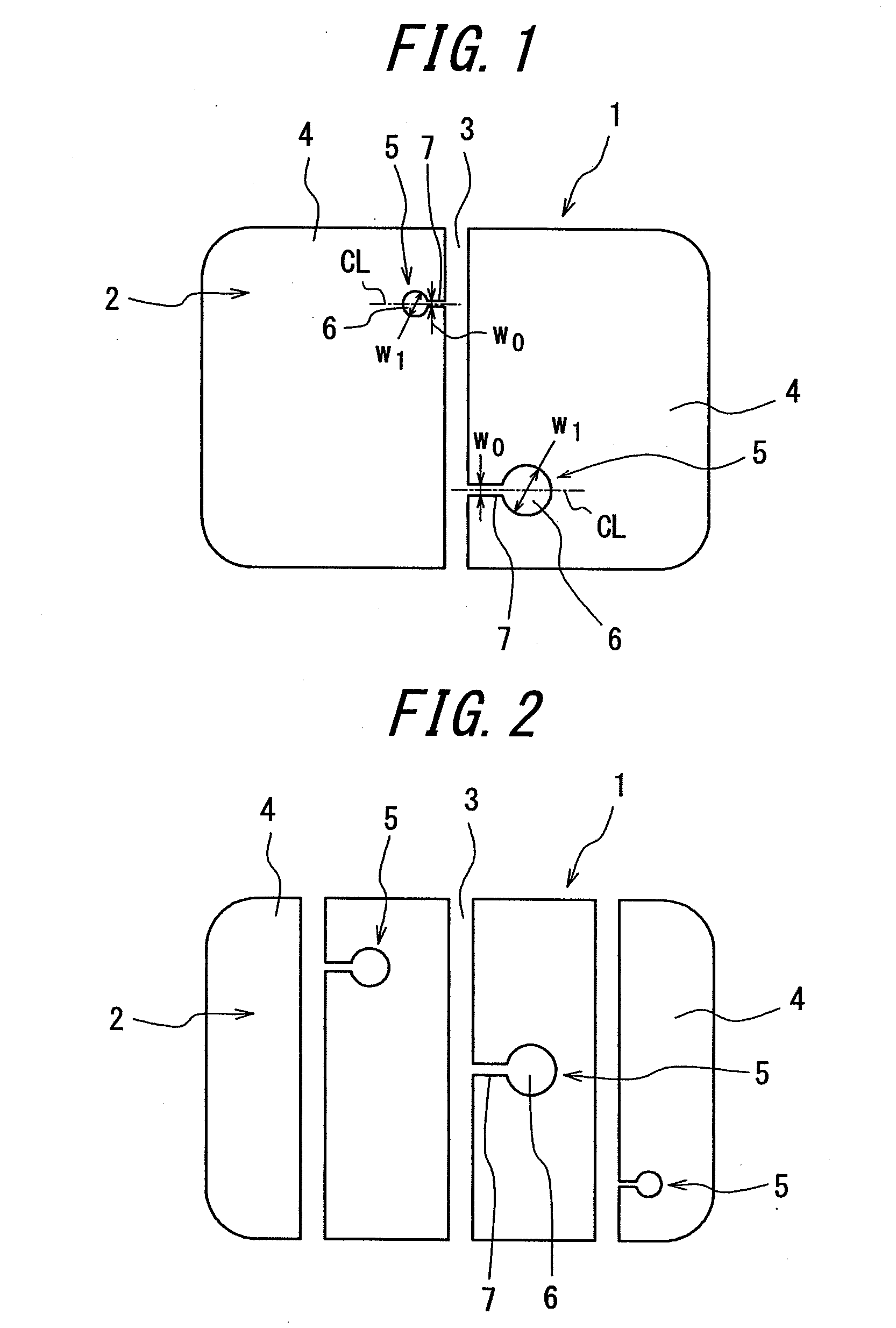
A pneumatic tire is provided which has sufficient total properties and mass productivity of a tire without reducing drainage capability due to narrowed circumferential grooves, achieves high design flexibility of tread patterns and stiffness of land portion as intended, and also effectively reduces undesired air column resonancenoise produced by the circumferential grooves. The pneumatic tire includes a circumferential groove 3 which continuously and circumferentially extends in a straight line and arranged on a tread 1, and resonators 5 which are open to the circumferential groove 3 and terminate in a land portion 4, each of the resonators 5 being configured with an air chamber 6 open toward a land portion surface, and a narrowed neck 7 for communication between the air chamber 6 and the circumferential groove 3, and the narrowed neck 7 has the plane maximum width w0 which is within a range of from 3 to 50% of the plane maximum width w1 of the air chamber 6.
Description
TECHNICAL FIELD[0001]The present invention relates to a pneumatic tire, more particularly, a tire for passenger vehicle, and specifically proposes a technique for efficiently reducing the air column resonancenoise generated by a circumferential groove which continuously and circumferentially extends in a straight, zigzag, or crank line on a tread of a tire, under the action of resonators.RELATED ART[0002]Air column resonancenoise is an undesired sound produced by the resonance of the air in a tube which is surrounded by a circumferential groove which continuously and circumferentially extends on a tread surface of a tire and the road surface within a ground-contact region of the tread surface, and the air column resonance noise is usually observed at frequencies within a range on the order of 800 to 1200 Hz in a general passenger vehicle, and because of a high peaksound pressure and a broad frequency band of the noise, the air column resonance noise constitutes the majority of th...
Claims
Application Information
Patent Timeline
Application Date:The date an application was filed.
Publication Date:The date a patent or application was officially published.
First Publication Date:The earliest publication date of a patent with the same application number.
Issue Date:Publication date of the patent grant document.
PCT Entry Date:The Entry date of PCT National Phase.
Estimated Expiry Date:The statutory expiry date of a patent right according to the Patent Law, and it is the longest term of protection that the patent right can achieve without the termination of the patent right due to other reasons(Term extension factor has been taken into account ).
Invalid Date:Actual expiry date is based on effective date or publication date of legal transaction data of invalid patent.

