Radiation detector and method for manufacturing the same

Active Publication Date: 2010-05-13
CANON ELECTRON TUBES & DEVICES CO LTD
View PDF4 Cites 9 Cited by
  • Summary
  • Abstract
  • Description
  • Claims
  • Application Information

AI Technical Summary

Benefits of technology

[0013]In the method of applying a reflective film containing light-scattering particles, such as TiO2 particles' and binder resin, spaces among particles of the light-scattering substance are densely filled with the resin binder. Therefore, the light-scattering effect of the light-scattering substance such as TiO2, which has a high refractive index, or the like is largely decreased. The reason for this is that as compared to the difference in refractive index between TiO2, which has a high refractive index (refractive index 2.7), and the atmosphere (refractive index 1.0), the difference in refractive index (another refractive index difference) between TiO2 (refractive index 2.7) and the resin binder (refractive index approximately 1.6) is small. Accordingly, the less the difference in the refractive indexes between TiO2 particles and the surrounding substance, the smaller the refraction angles or the reflection probability at the interfaces.
[0014]Light-scattering particles change the direction of travel of light at random by repeated interface reflection and refraction between the light-scattering particles and the surrounding substance. This effect allows the film formed using the light-scattering particles to play the role of reflective film. As described previously herein, if the spaces are filled with the binder resin such that the spaces are eliminated as usual, the refractive index difference at the interface between the light-scattering particles and the surrounding substance (=binder resin) reduces. This reduction results in increasing the average number of reflection and refraction required for changing the light direction to a certain extent. In other words, it means that a detour needs to be made so that the direction of fluorescence is changed to the same extent. The detour leads to diffusion of fluorescence far away both in the film thickness direction and the film plane direction of the reflective film. Therefore, through the inside of the reflective film, fluorescent cross-talk among pillars increases, reducing the resolution. Reduction in brightness of the fluorescence due to the detour is also caused in the inside of the reflective film.

Problems solved by technology

However, with a method of forming a metal layer on a scintillation layer as used conventionally, there is one unavoidable problem of low reflectance because of the influence of the surface roughness on the scintillation layer.
In these cases, however, the near surface region of the scintillation layer is impaired because such planarization causes a dead layer or an inefficient layer for scintillation.
Also, although pillars of the scintillation layer is separated to provide improvement of the resolution due to a light guide effect, intrusion of the resin protective film into the spaces among pillars diminish the light guide effect, leading to decrease of the resolution.
Disadvantages in these cases are serious.
With a method of placing a reflective plate on a scintillation layer, differences in spaces between a reflective plate and a scintillation layer causes un-uniformity in effective luminance and resolution.
But there are problems such as penetration of the resin into spaces among pillars of the scintillation layer, which leads to decrease in resolution.
Therefore, through the inside of the reflective film, fluorescent cross-talk among pillars increases, reducing the resolution.

Method used


Image

  • Radiation detector and method for manufacturing the same
  • Radiation detector and method for manufacturing the same
  • Radiation detector and method for manufacturing the same

Examples


Embodiment Construction

[0055]Embodiment of the present invention will be described below with reference to the accompanying drawings.

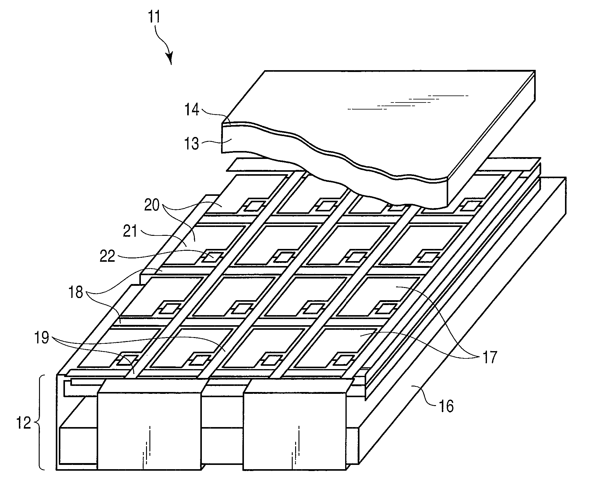
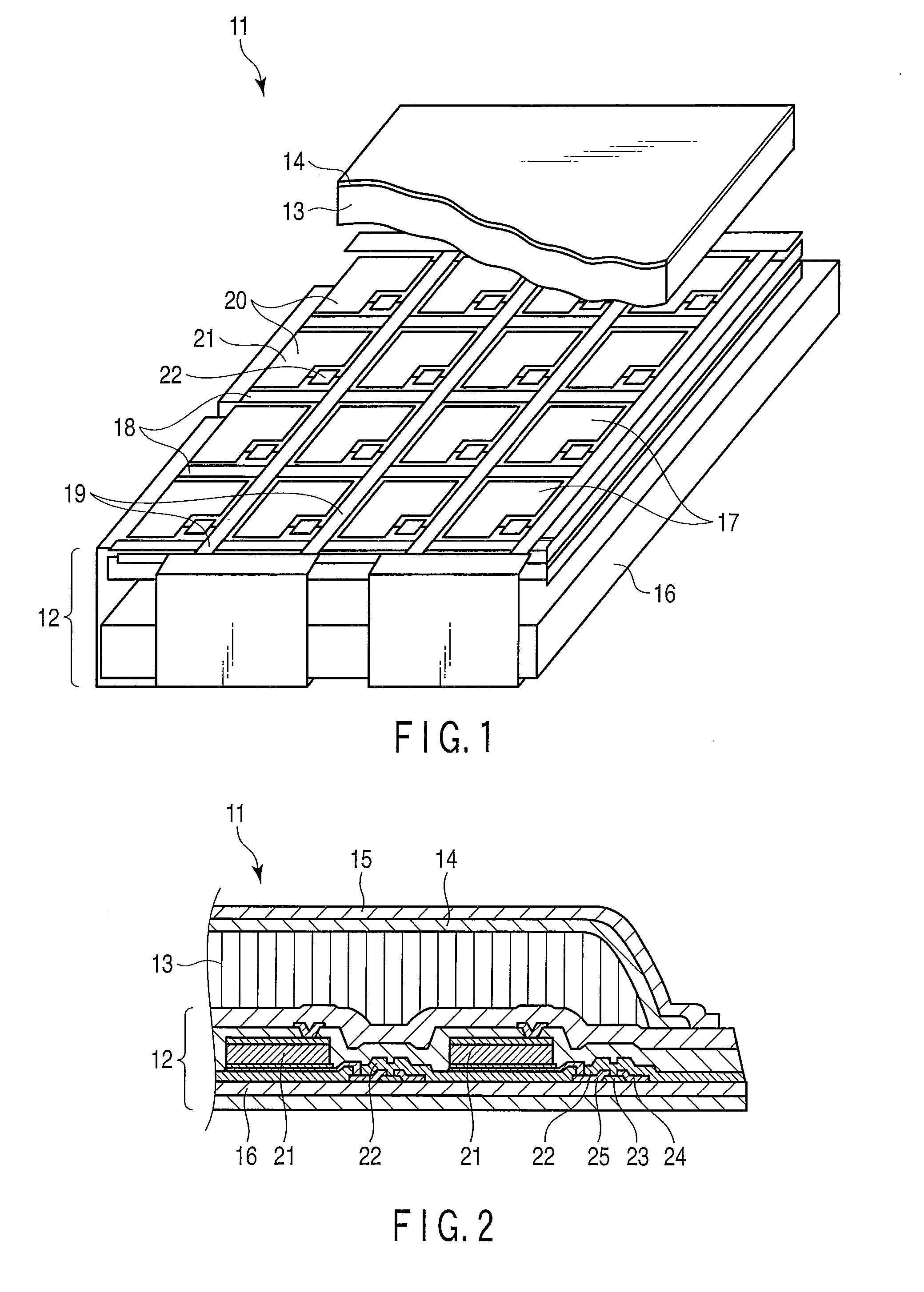
[0056]FIG. 1 is a perspective view of an X-ray detector 11 as a radiation detector, and FIG. 2 is a cross-sectional view of the X-ray detector. The X-ray detector 11 is an X-ray plane sensor for detecting an X-ray image as a radiological image, and is used, for example, for general medical applications. The X-ray detector 11 includes an array substrate 12 functioning as a photoelectric conversion substrate for converting fluorescence to an electrical signal, a scintillation layer 13 that is provided on the front surface, or one main surface, of the array substrate 12 and functions as an X-ray conversion unit for converting incident X-rays to fluorescence, and a reflective film 14 that is provided on the scintillation layer 13 and reflects fluorescence from the scintillation layer 13 toward a side of the array substrate 12. The X-ray detector 11 includes a moisture proof film...


PUM


Abstract

A radiation detector characterized by includes a photoelectric conversion element, a scintillation layer which converts radioactive rays to fluorescence, the scintillation layer being formed on the photoelectric conversion element, and a reflective film formed on the scintillation layer, the reflective film containing light-scattering particles for reflecting the fluorescence from the scintillation layer and a binder material binding the light-scattering particles, and having depletion portions without being filled with the binder material, the depletion portions being formed in a periphery of the light-scattering particles.

Description

CROSS REFERENCE TO RELATED APPLICATIONS[0001]This is a Continuation Application of PCT Application No. PCT / JP2008 / 063292, filed Jul. 24, 2008, which was published under PCT Article 21(2) in Japanese.[0002]This application is based upon and claims the benefit of priority from prior Japanese Patent Application No. 2007-194590, filed Jul. 26, 2007, the entire contents of which are incorporated herein by reference.BACKGROUND OF THE INVENTION[0003]1. Field of the Invention[0004]The present invention relates to a radiation detector for detecting radioactive rays and a method for manufacturing the radiation detector.[0005]2. Description of the Related Art[0006]A flat X-ray detector using an active matrix has been developed as a new-generation detector for X-ray diagnosis. Detecting X-rays impinging on the X-ray detector causes an X-ray radiographic image or a real-time X-ray image to be output as digital signals. In the X-ray detector, X-rays are converted to visible light, that is, fluore...

Claims


Application Information

Patent Timeline
IPC IPC(8): G01T1/20H01L31/0232
CPCH01L27/1446H01L27/14625G01T1/2002H01L27/14663G01T1/20H01L27/14H01L31/09
Inventor HOMMA, KATSUHISAFUJIEDA, SHINETSU
Owner CANON ELECTRON TUBES & DEVICES CO LTD
Why Eureka
Try Eureka