Air-oil heat exchanger placed at the location of the air separator nose of a turbojet, and a turbojet including such an air-oil heat exchanger

a technology of air separator nose and air-oil heat exchanger, which is applied in the direction of air transportation, stationary conduit assembly, engine cooling apparatus, etc., can solve the problems of air-oil heat exchanger being nowadays unavoidable, increasing drag of the airplane, and dropping in the overall efficiency of the engine, so as to achieve no risk of being damaged

Inactive Publication Date: 2009-07-02
TECHSPACE AERO
View PDF12 Cites 106 Cited by
  • Summary
  • Abstract
  • Description
  • Claims
  • Application Information

AI Technical Summary

Benefits of technology

[0015]An object of the invention is to provide an air-oil heat exchanger making it possible to satisfy needs for cooling the oil circuit of the turbojet, while also preventing icing of the separator nose, and to do this without significantly disturbing the air stream.
[0019]Thus, in particular by incorporating the oil circuit inside the separator nose, use is made of available space while minimizing disturbance to the air stream by the fins.
[0021]In addition to cooling the oil circuit, this solution presents the additional advantage of de-icing the separator nose. The air-oil heat exchanger of the invention forms an anti-icing device for the separator nose and for the inlet guide vanes (IGVs) situated beneath the bottom portion of the separator nose, making use of the heat delivered by the oil circuit to the front portion of the separator nose.
[0023]It should be observed that since the air-oil heat exchanger of the invention is situated downstream from the fan and in the portion situated towards the inside of the secondary duct, it has practically no risk of being damaged by foreign bodies penetrating into the turbojet, since it is the fan that absorbs the impact, and by its rotary motion breaks such bodies into small pieces, which pieces are then entrained downstream from the fan and by centrifugal force towards the outside of the secondary duct.

Problems solved by technology

Nevertheless, not only is the drag of the airplane increased when using a scoop external to the engine, but the aerodynamic disturbance imparted to the air stream by an air takeoff also leads to a drop in the overall efficiency of the engine.
However, such an air-oil heat exchanger is nowadays unavoidable as an additional system for cooling the oil of the engine circuit, over and above the cooling performed by the oil-fuel heat exchangers.
Nevertheless, installing such heat exchangers can lead to constraints involving integration with the walls of the duct (housings, pod cowls), or to a reduction in the areas that are effective in treating sound.
That solution does not enable the separator nose to be de-iced, nor does it optimize the aero-thermal performance of the heat exchanger.
Nevertheless, such a solution would not provide sufficient oil cooling capacity if it were to be implemented in the separator nose.
The drawback of that type of solution is that it gives rise to a loss of efficiency associated with tapping the air, and it represents an additional weight.

Method used


Image

  • Air-oil heat exchanger placed at the location of the air separator nose of a turbojet, and a turbojet including such an air-oil heat exchanger
  • Air-oil heat exchanger placed at the location of the air separator nose of a turbojet, and a turbojet including such an air-oil heat exchanger
  • Air-oil heat exchanger placed at the location of the air separator nose of a turbojet, and a turbojet including such an air-oil heat exchanger

Examples


first embodiment

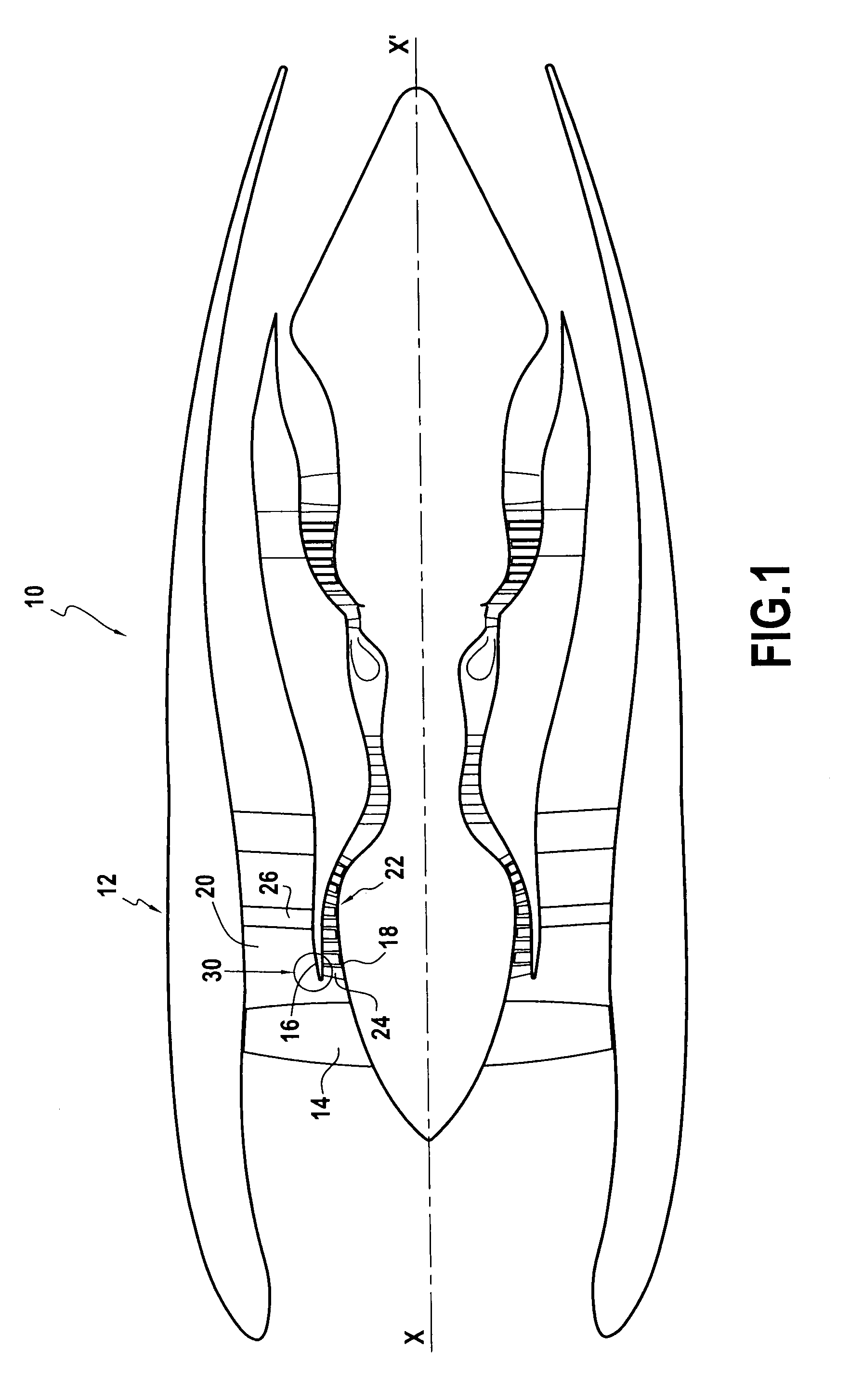
[0053]In the first embodiment shown in greater detail in FIG. 2, the oil circuit 43 passes inside the top wall 162 of the separator nose 16 and inside the bottom wall 163 of the separator nose 16.

[0054]In this first embodiment, the oil circuit 43 forms a coil disposed within the thickness of the top wall 162 and of the bottom wall 162 of the separator nose 16.

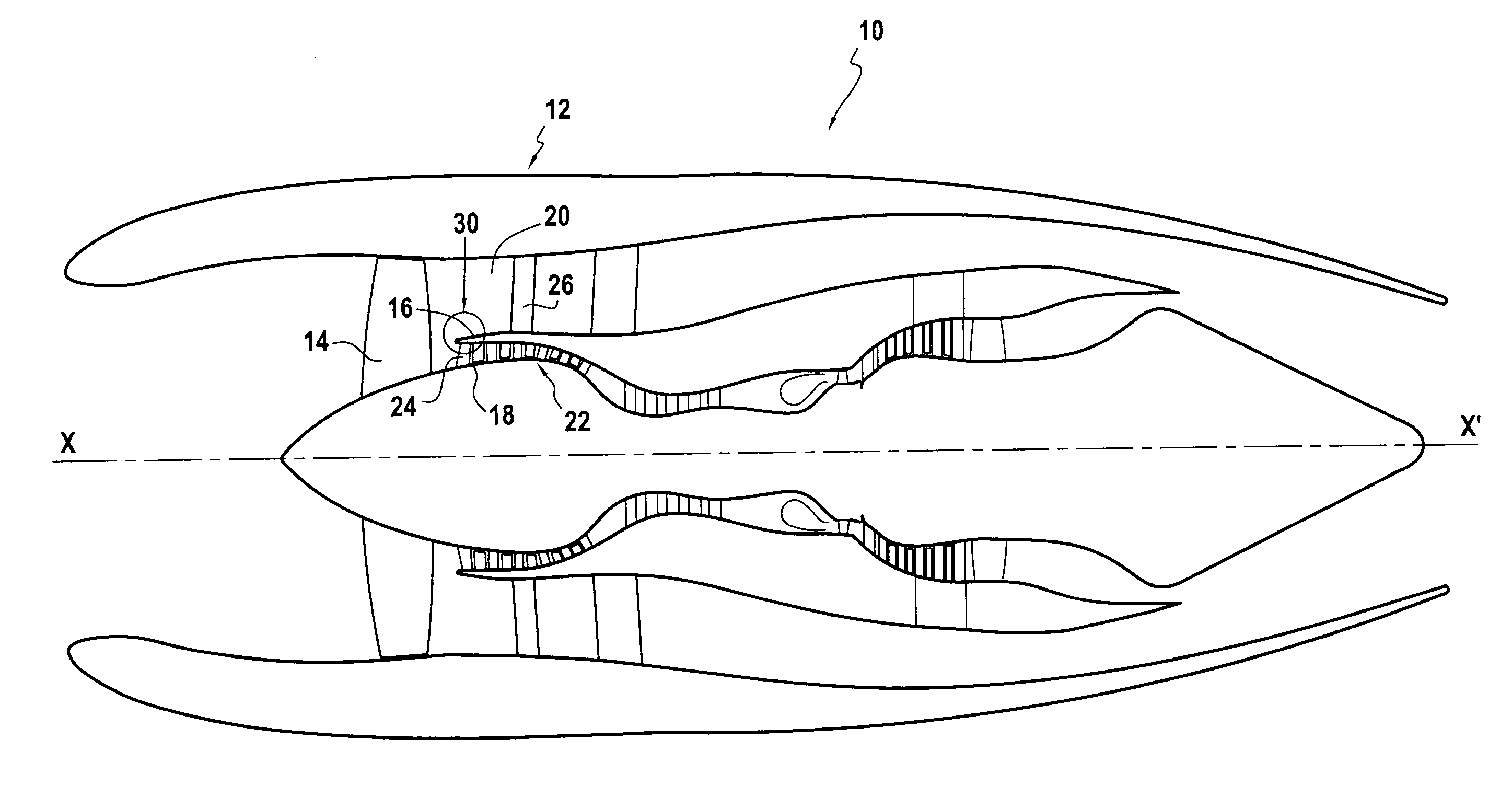
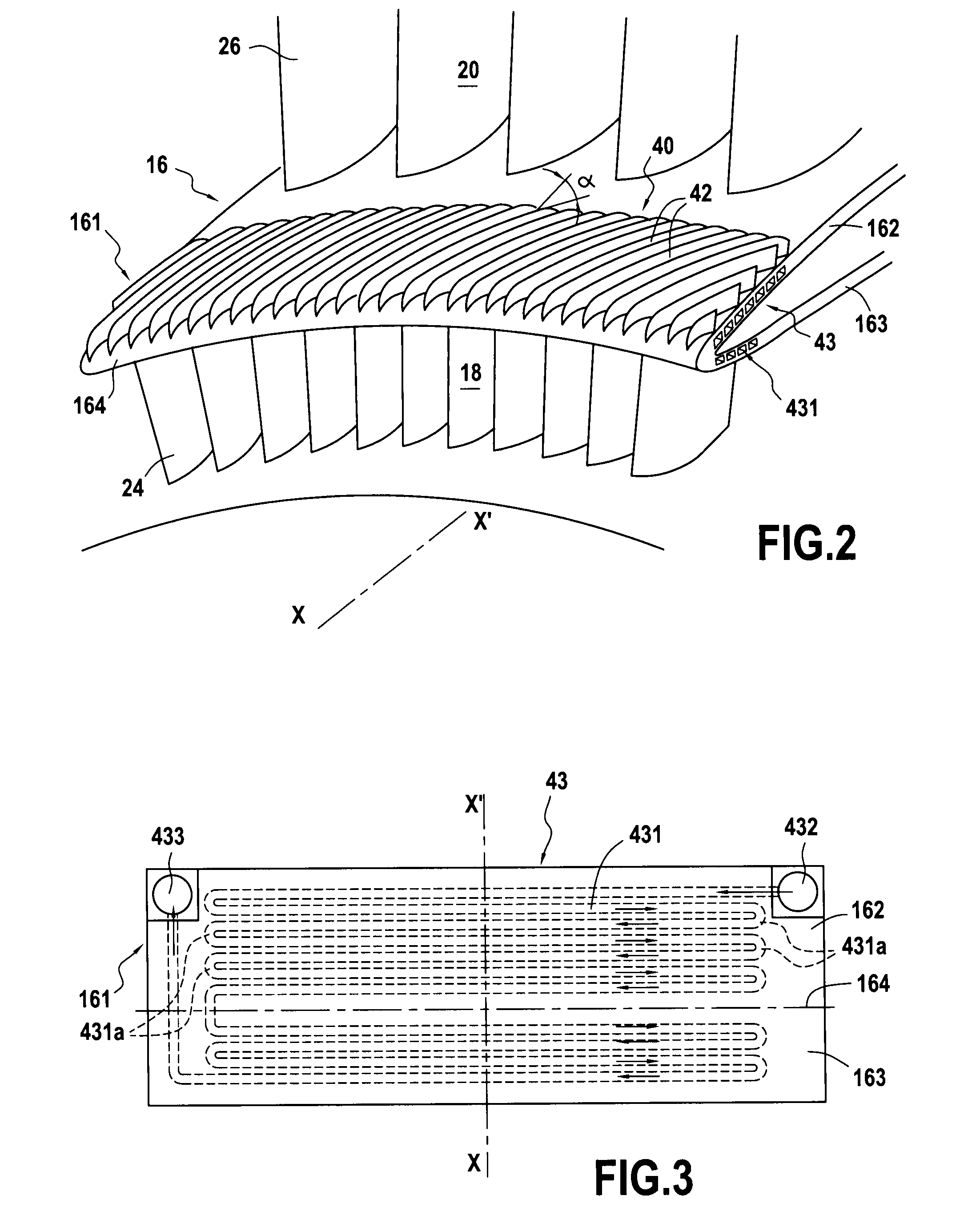
[0055]In the configuration shown in FIGS. 2 and 3, the oil circuit 43 travels along the front portion 161 of the separator nose 16 in an essentially circumferential manner, with segments 431 of the oil circuit 43 being annular about the axis (X-X′) of the turbojet and mutually parallel. These almost annular circumferential segments 431 are interconnected by bends 431a (see FIG. 3) so that the oil flow goes from one segment 431 of the oil circuit 43 to the next in a direction opposite to the flow direction of the secondary air stream.

[0056]By way of example, these segments 431 of the oil circuit 43 may be hollow channels formed ...

second embodiment

[0077]In another variant (not shown) of this second embodiment, only the first oil flow unit 43a′ is used.

[0078]In the variant of the first embodiment or of the second embodiment in which the oil circuit is present only at the location of the top wall 162 of the separator nose 16, provision can be made, as shown in FIG. 9 for the first embodiment, for the air-oil heat exchanger 40 also to include a thermal bridge 50 interconnecting the top wall 162 and the bottom wall 163 of the front portion 161 of the separator nose 16.

[0079]In FIG. 9, this thermal bridge 50 is a plate interconnecting the bottom face of the top wall 162 in the oil circuit zone to the top face of the bottom wall 163. The thermal bridge 50 is made of one or more materials that are good conductors of heat, such as aluminum.

[0080]As a result, there is better transfer heat between the top wall 162 and the bottom wall 163 because of the heat that is conducted via the thermal bridge from the oil circuit of the top wall 1...


PUM


Abstract

The invention relates to an air-oil heat exchanger located at the inner shroud of the secondary duct of a turbojet. In characteristic manner, it comprises an oil circuit placed inside the separator nose and fins placed outside the top wall of the separator nose, between the leading edge of the separator nose and the outlet guide vanes.

Description

FIELD OF THE INVENTION[0001]The invention relates to an air-oil heat exchanger for cooling the oil of an engine and / or of equipment installed in the engine (electrical equipment, gearboxes, etc.), the heat-exchanger being located at the inner shroud of the secondary duct of a turbojet, preferably at the location of the air separator nose.[0002]The invention also relates to a turbojet including such an air-oil heat exchanger.BACKGROUND OF THE INVENTION[0003]The air separator nose situated downstream from the fan serves to separate the primary air stream flowing in the primary duct from the secondary air stream flowing in the secondary duct.[0004]In a turbomachine, various members and pieces of equipment need to be lubricated and / or cooled, with the heat generated generally being conveyed by oil systems and being dumped by oil-cooled or air-cooled heat exchangers. An air-cooled oil cooler (ACOC) involves forcing a stream of air over a heat exchange surface added to the oil circuit.[00...

Claims


Application Information

Patent Timeline
Patent Type & Authority Applications(United States)
IPC IPC(8): F01N5/02F02C7/14F02C7/12F02C1/00
CPCF01D25/02F01D25/12F01D25/18F02C7/047F02K3/06Y02T50/675F28D2021/0089F28F1/34F28F3/02F28F3/12Y02T50/671F28D1/03F02C7/14Y02T50/60
Inventor BAJUSZ, DENISCORNET, ALBERTFRIEDEL, JEROMERAIMARCKERS, NICOLAS
Owner TECHSPACE AERO
Why Eureka
Try Eureka