
Hybrid electric vehicle

a hybrid electric vehicle and electric motor technology, applied in the direction of propulsion parts, electric propulsion mounting, transportation and packaging, etc., can solve the problems of wasting energy, wasting energy, and wasting energy, so as to achieve the effect of quickly and smoothly starting the engin

Inactive Publication Date: 2009-07-02
DUAN ZHIHUI +1
View PDF14 Cites 52 Cited by
  • Summary
  • Abstract
  • Description
  • Claims
  • Application Information

AI Technical Summary

Benefits of technology

[0018]When the torque-limiting device is disengaged, the motor can drive the vehicle solely, without rotating the engine, so no energy loss is caused due to engine's friction and air-pumping torque.
[0022]The system can start the engine and generate electricity while the vehicle is at still. The motor can drive the vehicle while the engine is off, and the system can start the engine quickly and smoothly while the vehicle is running. When working, the engine can drive the vehicle in the same way as in a conventional vehicle and provide power for the motor to generate electricity. The motor can assist the engine to drive and apply re-generative braking.

Problems solved by technology

When cruising on a flat road, the vehicle only needs relatively small power or torque to maintain its speed, but it takes much more power or torque to accelerate or go uphill.
Usually a bigger engine loss more energy due to friction than a smaller one.
On the other hand, high power is needed only for a small fraction of working time, so for most of the time, a significantly small engine will work well for the vehicle, and it can save a lot of energy.
When the vehicle applies braking, the kinetic energy of the vehicle is converted into heat, and a lot of energy is lost.
Also, when a conventional vehicle stops at traffic light, the engine keeps running, burning out fuel unnecessarily.
One drawback to such a system is that the motor shaft is fixedly attached to the engine shaft.
This is inefficient because an increased amount of power must be provided.
One drawback to such a system is that: it takes many steps and a long time to start the engine while the vehicle is running.
This is a significant issue for the vehicle's performance.

Method used


Image

  • Hybrid electric vehicle
  • Hybrid electric vehicle
  • Hybrid electric vehicle

Examples


first preferred embodiment

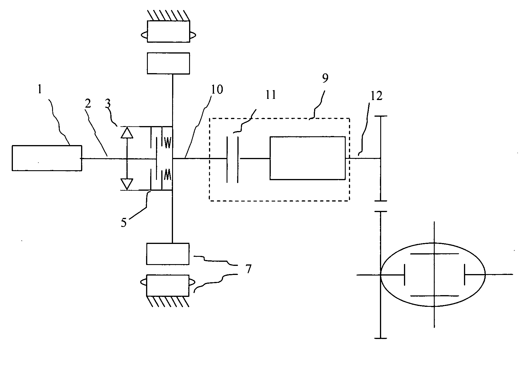
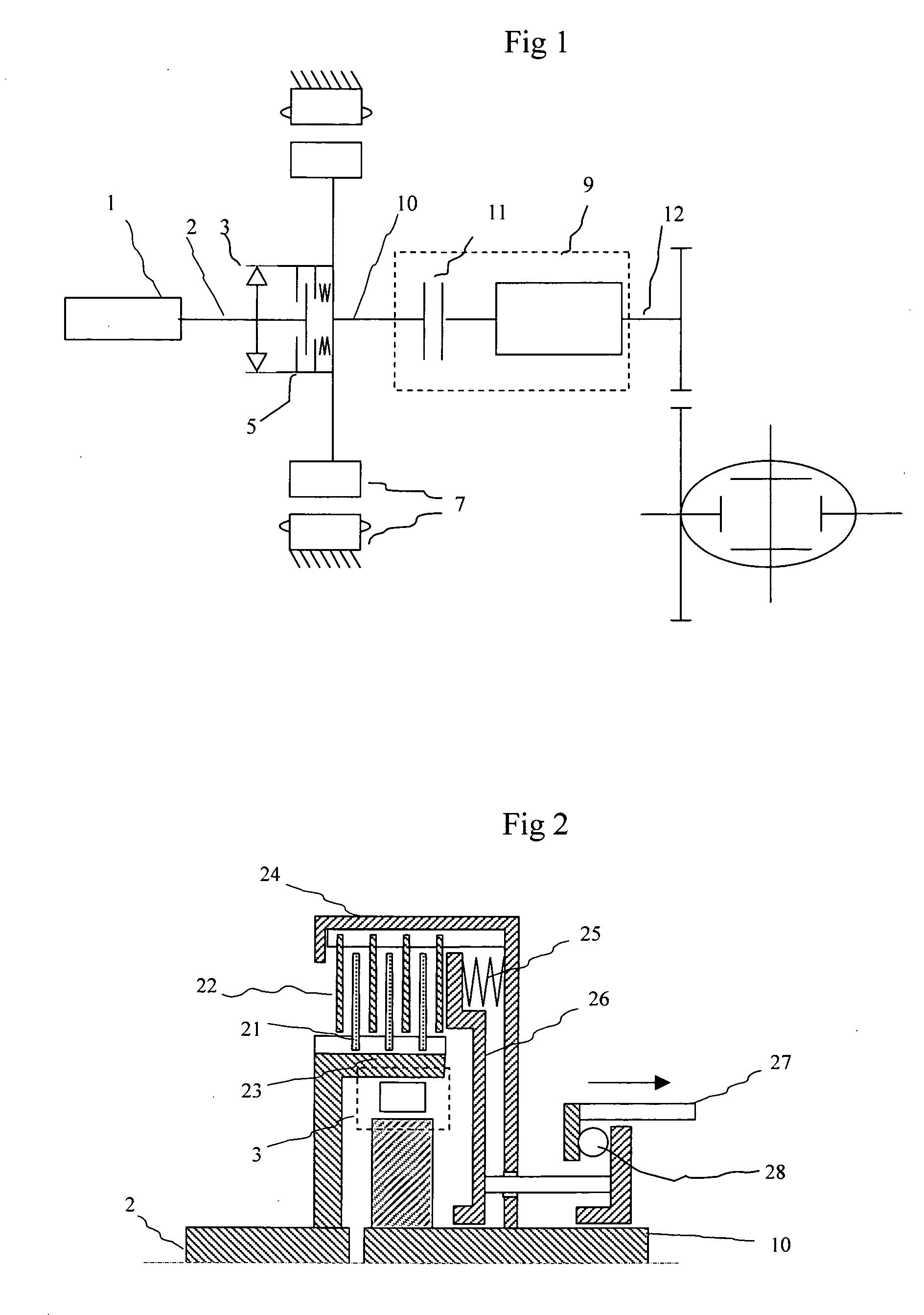
[0027]FIG. 1 shows the schematic view of a hybrid electric drive system according to a first preferred embodiment of the present invention. The hybrid electric drive system comprises: a heat engine 1 with an output shaft 2, a one-way-clutch 3, a torque-limiting device 5, an electric motor 7, and a transmission 9.

[0028]Engine 1 converts fuel energy into mechanical energy and outputs torque through engine shaft 2.

[0029]Motor 7 can convert the electric energy from a set of power battery (not shown) into mechanical energy and outputs torque through a motor shaft 10. It can also output braking torque during deceleration and, at the same time, recover the kinetic energy of the vehicle into electric energy for the battery to store.

[0030]Transmission 9 has an input shaft connected to motor shaft 10 and an output shaft 12, and output shaft 12 is connected to vehicle's wheels.

[0031]One-way-clutch 3 is disposed between engine shaft 2 and motor shaft 10, and it can transmit forward torque from ...

second preferred embodiment

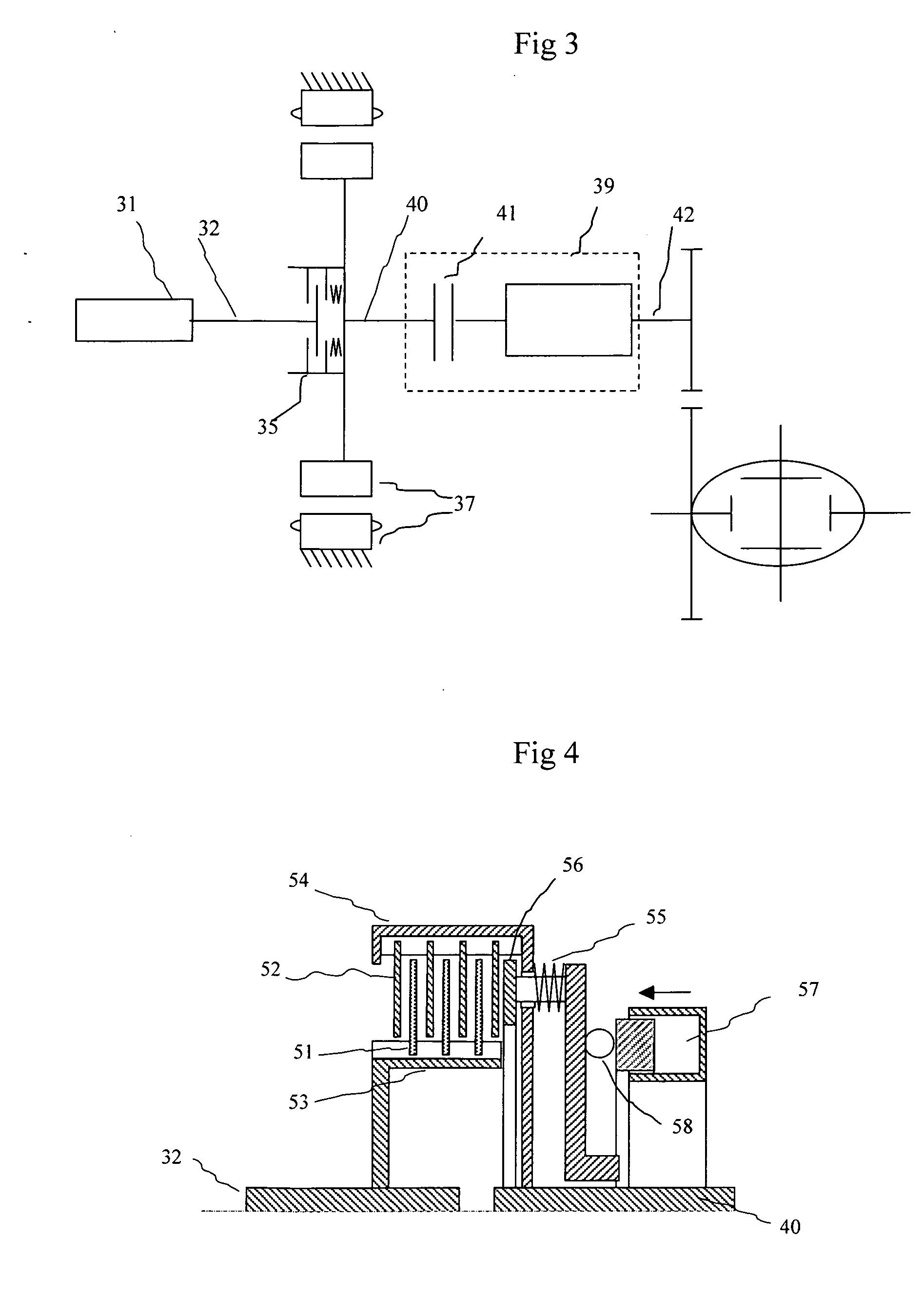
[0047]FIG. 3 shows the schematic view of a hybrid electric drive system according to a second preferred embodiment of the present invention. The hybrid drive system comprises: a heat engine 31 with an output shaft 32, a torque-control device 35, an electric motor 37, and a transmission 39.

[0048]Engine 31 converts fuel energy into mechanical energy and outputs torque through engine shaft 32.

[0049]Motor 37 can convert the electric energy from a battery (not shown) into mechanical energy and outputs torque through a motor shaft 40. It can also output braking torque during deceleration and, at the same time, recover the kinetic energy of the vehicle into electric energy for the battery to store.

[0050]Transmission 39 has an input shaft connected to motor shaft 40 and an output shaft 42, and output shaft 42 is connected to vehicle's wheels.

[0051]Torque-control device 35 selectively disengages, partially engages and fully engages engine shaft 32 with motor shaft 40.

[0052]When torque-contro...


PUM


Abstract

A hybrid electric drive system for an automotive vehicle comprises a heat engine, an electric motor, a one-way-clutch, a torque-limiting clutch, and a transmission. The one-way-clutch disposed between the engine shaft and the motor shaft, and it can transmit torque from the engine shaft to the motor shaft. The transmission has an input shaft being connected to the motor shaft and an output shaft to drive the wheels. The torque-limiting clutch is also disposed between the engine shaft and the motor shaft. When it is disengaged, the torque-limiting clutch disconnects the motor shaft from the engine shaft, so the motor can solely drive the vehicle. When it is engaged, the clutch transmits a pre-determined level of torque from the motor shaft to the engine shaft in order to start the engine. The torque limiting clutch will smooth out the torque peak when the system starts the engine while the vehicle is running.

Description

CROSS-REFERENCE TO RELATED APPLICATION[0001]This application claims the benefit of PA Ser. Nr. 200720302330.1, filed Dec. 28, 2007 in P. R. China by the present inventor.FEDERALLY SPONSORED RESEARCH[0002]Not ApplicableSEQUENCE LIST OR PROGRAM[0003]Not ApplicableTECHNICAL FIELD[0004]The present invention relates to hybrid electric vehicles, and more specifically, to a hybrid electric vehicle having an electric motor that is coupled between the engine and transmission.BACKGROUND OF THE INVENTION[0005]In a conventional vehicle, an internal combustion engine generates rotary power by burning fuel, and the power is transmitted to the driving wheels through a mechanical transmission. The engine is the only power supply to the vehicle and has to provide all the torque that the vehicle needs. When cruising on a flat road, the vehicle only needs relatively small power or torque to maintain its speed, but it takes much more power or torque to accelerate or go uphill. The engine has to be able...

Claims


Application Information

Patent Timeline
Patent Type & Authority Applications(United States)
IPC IPC(8): B60K1/00
CPCB60K6/383B60K6/387B60K6/48B60L2240/441B60W10/02B60W10/06Y02T10/6286B60W20/00B60W20/40B60W2510/0638B60W2520/10B60W2710/025Y02T10/6221B60W10/08B60K2006/268B60K2006/4825Y02T10/62
Inventor DUAN, ZHIHUIZHANG, LINGLING
Owner DUAN ZHIHUI
Learn More