
Electrode for electrochemical device and electrochemical device

Inactive Publication Date: 2009-07-02
TDK CORPARATION
View PDF5 Cites 5 Cited by
  • Summary
  • Abstract
  • Description
  • Claims
  • Application Information

AI Technical Summary

Benefits of technology

[0005]During winding, same-polarity leads have conventionally been disposed on the collector overlapping substantially with each other, without paying special attention to the arrangement spacing between leads or to the number of leads thus arranged. To be used with greater efficiency, the electrochemical device must exhibit lower impedance. In terms of lowering the impedance of the electrochemical device, it may presumably suffice to reduce the contribution of the collector to resistance, by simply increasing the number of leads and narrowing the lead arrangement spacing.
[0013]Such an electrode for electrochemical devices affords an electrochemical device having low impedance and low leakage current.

Problems solved by technology

However, the inventors have found that leakage current increases when the lead arrangement spacing is too narrow.
An increase in leakage current is accompanied by energy loss, and is thus undesirable.

Method used


Image

  • Electrode for electrochemical device and electrochemical device
  • Electrode for electrochemical device and electrochemical device
  • Electrode for electrochemical device and electrochemical device

Examples


first embodiment

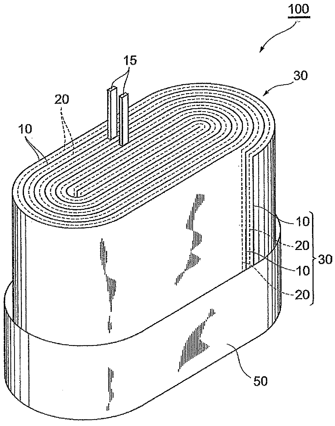
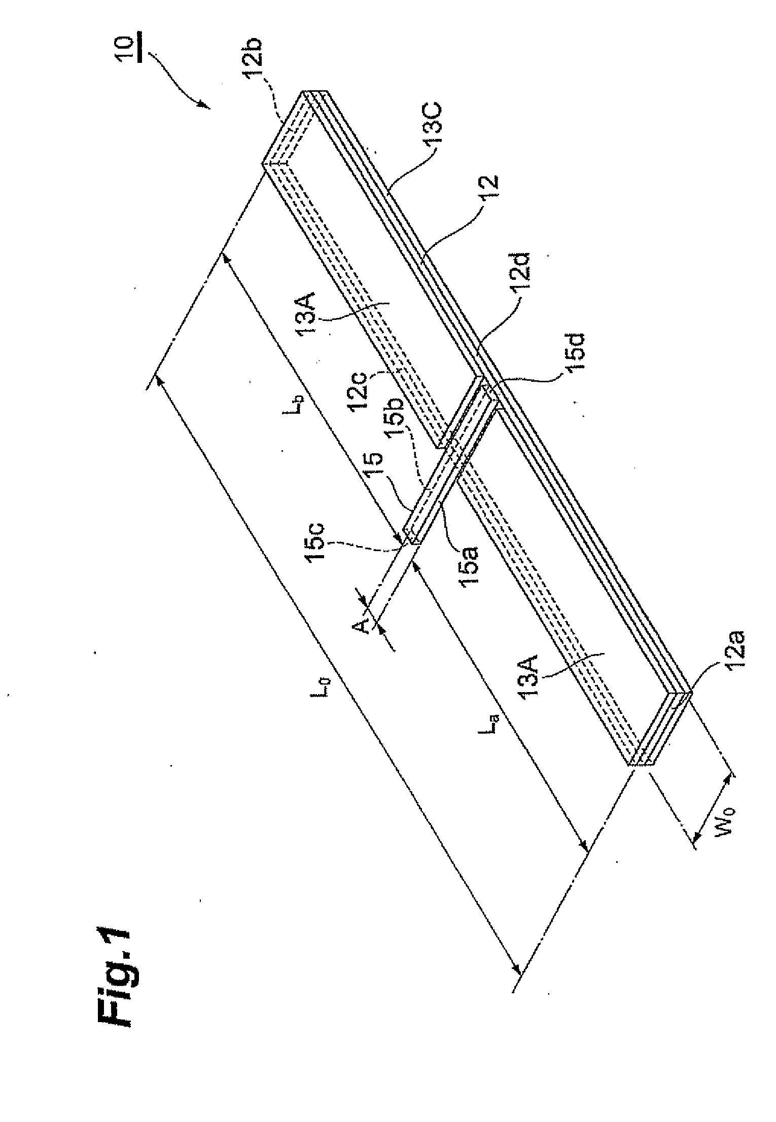
[0022]An electrode for electrochemical devices 10 according to a first embodiment will be explained with reference to FIG. 1. The electrode for electrochemical devices 10 comprises mainly a collector 12, active material layers 13A, 13C containing an active material, and a lead 15.

[0023]The collector 12 is a conductive member in the form of a rectangular elongated plate. Although not particularly limited thereto, the material of the collector is preferably a metallic material, such as copper, aluminum or nickel. For instance, the electric resistivity ρ of copper, aluminum and nickel are 1.68×10⁻⁸ Ωm, 2.65×10⁻⁸ Ωm, 6.99×10⁻⁸ Ωm, respectively. The thickness of the collector is not particularly limited, and may range from 10 to 50 μm. Also, the length L0 in the longitudinal direction and the length W0 in the direction (width direction) perpendicular to the longitudinal direction are not particularly limited. The length L0 in the longitudinal direction may range, for instance, from 80 to...

second embodiment

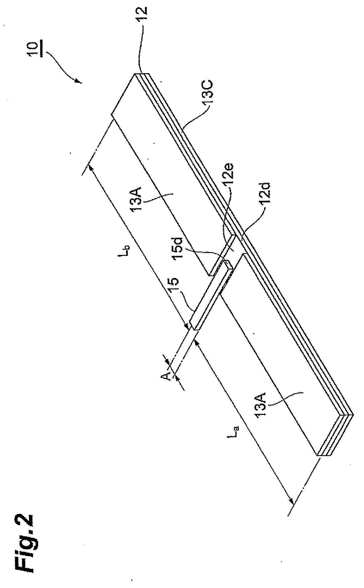
[0038]An electrode for electrochemical devices 10 according to a second embodiment is explained next with reference to FIG. 2. The electrode for electrochemical devices 10 according to the present embodiment differs from the electrode for electrochemical devices according to the first embodiment in the shape of the lead 15, and thus only this feature will be explained. In the lead 15 according to the second embodiment, the end face 15d does not protrude up to the side face 12d of the collector 12, but is positioned over the surface 12e of the collector 12. Such an electrode for electrochemical devices 10 elicits the same effect as that of the first embodiment.

third embodiment

[0039]An electrode for electrochemical devices 10 according to a embodiment is explained next with reference to FIG. 3. The electrode for electrochemical devices 10 according to the present embodiment differs from the electrode for electrochemical devices according to the first embodiment in the shape of the lead 15, and thus only is feature will be explained. The lead 15 according to the third embodiment is not provided on the front face or rear face of the collector 12 but on the side face 12d of the collector 12. As a result, the active material layer 13A is not split but formed as a singe unit, as is the case with the active material layer 13C. Such a lead 15 can be easily formed by cutting the collector 12 and the lead 15 out of a singe conductive plate. Such an electrode for electrochemical devices 10 elicits the same effect as that of the first embodiment.


PUM

PropertyMeasurementUnit
Temperatureaaaaaaaaaa
Angleaaaaaaaaaa

Abstract

An electrode for an electrochemical device, including an elongated collector, a lead provided halfway along a longitudinal direction of the collector, and active material layers provided on the collector, wherein when La (m) is a distance from one end of the collector, in the longitudinal direction, up to the lead, and Lb (m) is a distance from the other end of the collector, in the longitudinal direction, up to the lead, and ρ (Ωm) is a resistivity of the collector at 25°, where Lopt (m) being 1.9×10⁶ρ, the La (m) and Lb (m) are from 0.95 Lopt to 1.05 Lopt respectively.

Description

BACKGROUND OF THE INVENTION[0001]1. Field of the Invention[0002]The present invention relates to an electrode for electrochemical devices, and to an electrochemical device.[0003]2. Related Background Art[0004]Spirally wound electrochemical devices are formed by winding electrodes in the longitudinal direction, the electrodes being obtained by forming active material layers on an elongated collector. When the length of the collector in the longitudinal direction is substantial, the collector is provided with a plurality of leads, spaced apart from each other, in the longitudinal direction of the collector, in order to suppress heat generation, polarization and the like that result from concentration of large currents (see, for instance, Japanese Patent Application Laid-open Nos. H7-192717, H11-283882, H11-283883, H11-317218, 2000-106167, 2000-182656, 2000-110453, 2006-260892 and 2006-286404).SUMMARY OF THE INVENTION[0005]During winding, same-polarity leads have conventionally been di...

Claims


Application Information

Patent Timeline
IPC IPC(8): C25C7/02H01G11/66H01G11/70H01G11/74H01M4/13H01M4/66H01M50/533H01M50/536H01M50/538
CPCH01G9/008H01G9/016H01G9/06H01G9/151H01G11/72Y02E60/122H01M2/263H01M4/661H01M10/0431Y02E60/13H01G11/74Y02E60/10H01M50/538Y02P70/50H01M50/533H01M50/536
Inventor OHASHI, YOSHIHIKOHINOKI, KIYONORIKATAI, KAZUOKOBAYASHI, KEITA
Owner TDK CORPARATION
Learn More