Patch package structure

Active Publication Date: 2009-07-02
NITTO DENKO CORP +1
View PDF11 Cites 2 Cited by
  • Summary
  • Abstract
  • Description
  • Claims
  • Application Information

AI Technical Summary

Benefits of technology

[0057]The water vapor transmission rate of the acrylonitrile resin layer 12 can be adjusted by, for example, changing the film thickness, draw ratio of the film and the like.
[0058]Moreover, the acrylonitrile resin layer 12 does not allow easy adsorption of the organic liquid component in the adhesive layer of the patch and can suppress a decrease in the content of an organic liquid component in an adhesive layer during preservation. The effect becomes prominent when the organic liquid component has a low boiling point or is highly volatile.
[0059]As mentioned below, the packaging member of the present invention is produced, for example, by surrounding a patch with a package, and heat sealing the marginal of the package. Desirably, therefore, the acrylonitrile resin layer in the first package is imparted with the heat sealability.
[0060]In the present invention, an acrylonitrile resin to be used for the acrylonitrile resin layer 12 is not particularly limited as long as the acrylonitrile component constitutes 50 wt % or more of the total weight of the resin in the layer.
[0061]Accordingly, examples of the acrylonitrile resin include (i) polyacrylonitrile, (ii) a mixture or polymer alloy of polyacrylonitrile and the other resin, (iii) a copolymer wherein the main structural unit consists of acrylonitrile, or (iv) a composition obtained by combining at least two of the aforementioned (i)-(iii), and the like. From the aspects of suitable flexibility, rigidity and heat sealability as a package of a patch, one of the above-mentioned (ii)-(iv) is preferable.
[0062]Acrylonitrile makes it difficult for a

Problems solved by technology

However, since its form is flat and plane and has a large surface area, the quality of patch is susceptible to influence from the environment outside the patch.
However, such patch package structure may decrease the content of a physiologically active ingredient in the patch, since the innermost layer of the packaging member is made of LDPE, which absorbs the physiologically active ingredient.
In addition, since the LDP

Method used


Image

  • Patch package structure
  • Patch package structure
  • Patch package structure

Examples


example 1

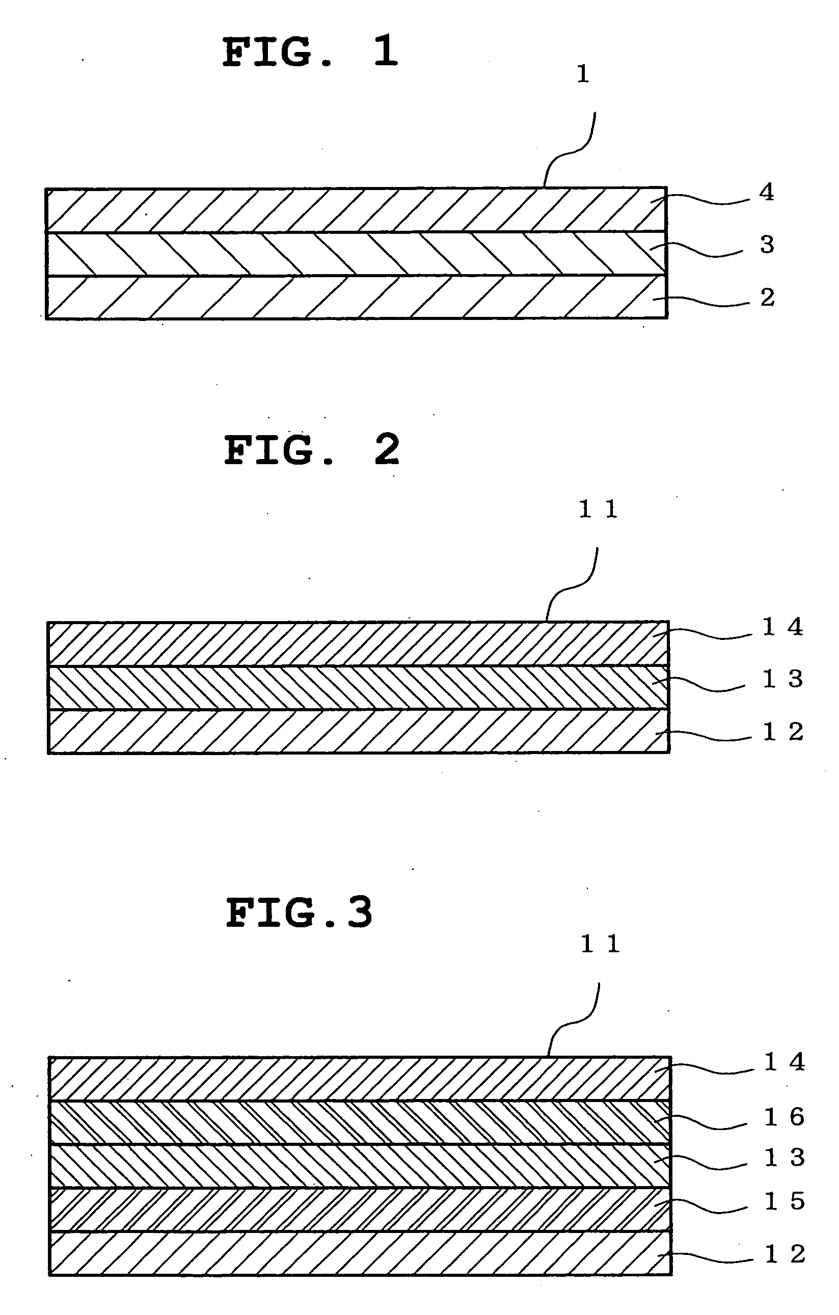
[0104]A sheet was produced by laminating 12 μm-thick PET film / 9 μm-thick AL foil / 20 μm-thick LDPE film / 30 μm-thick water-absorbing layer A / 10 μm-thick LDPE film / 30 μm-thick PAN film by dry lamination. The 20 μm-thick LDPE film / 30 μm-thick water-absorbing layer A / 10 μm-thick LDPE film was laminated by coextrusion inflation.

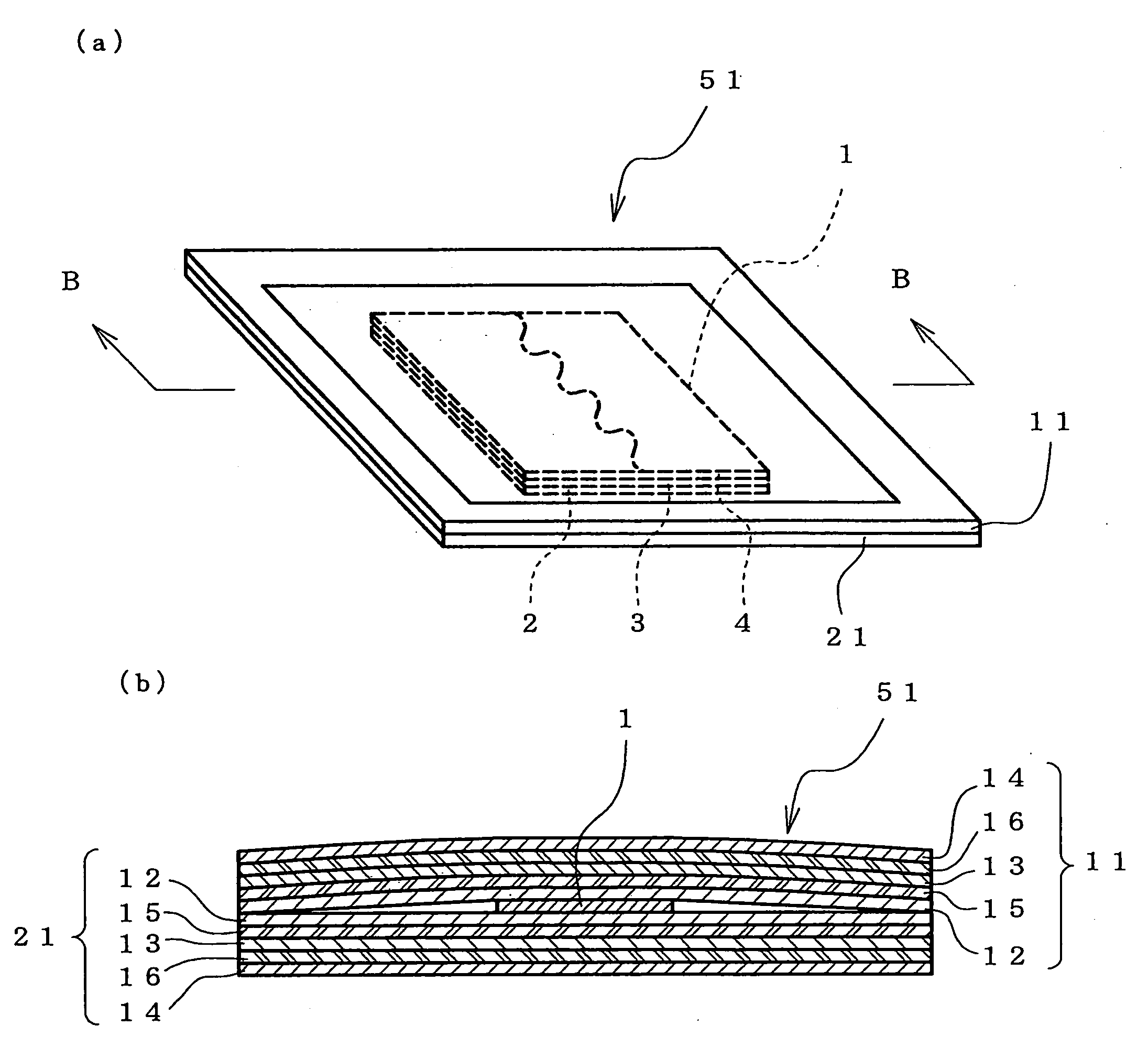
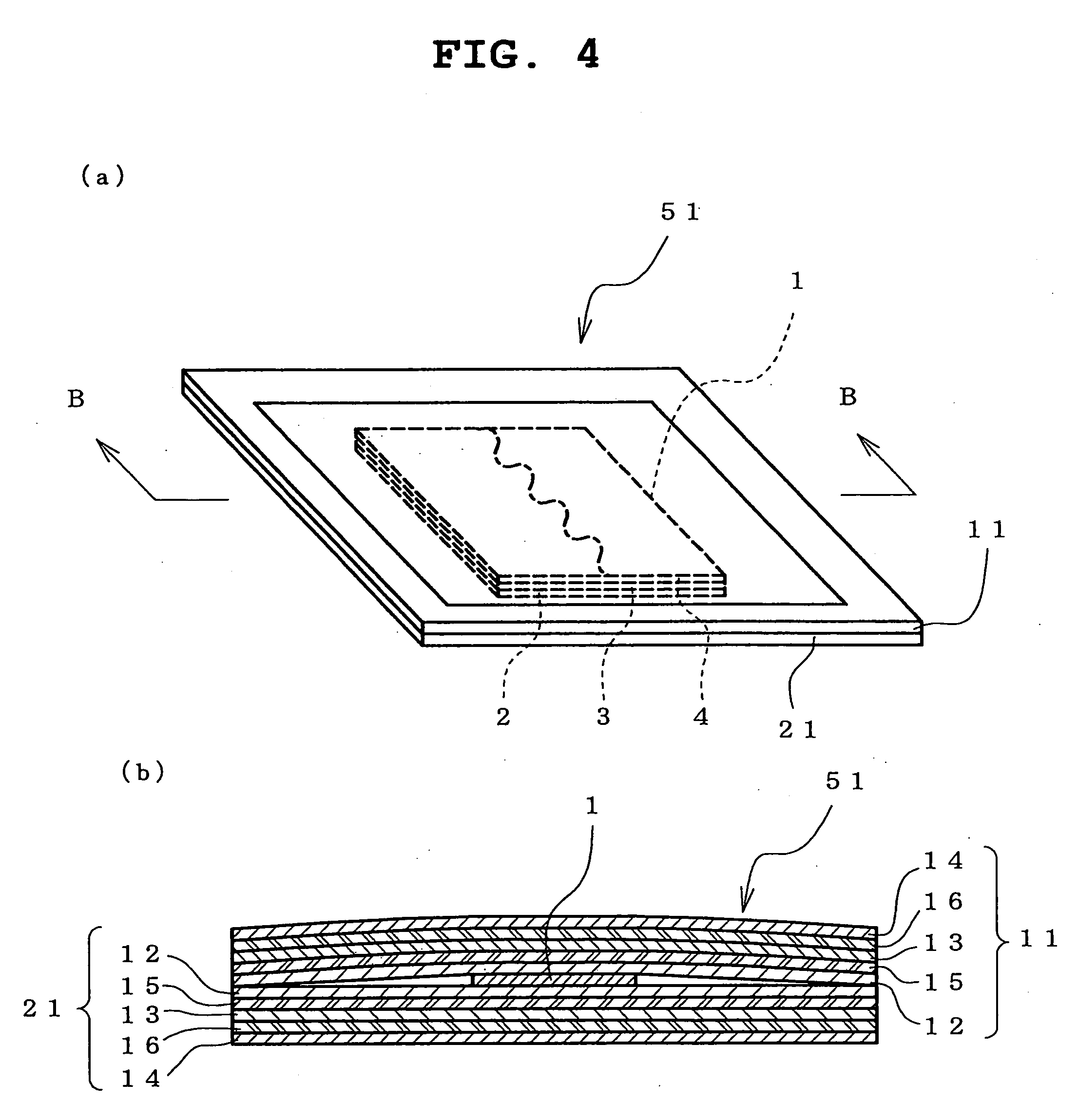
[0105]The sheet was cut into a 65 mm×65 mm about rectangle to give a first package. Similarly, moreover, the sheet was cut into a 65 mm×65 mm about rectangle to give a second package. The PAN surfaces of the first package and the second package were directly faced against each other, the patch prepared above, which was free of a physiologically active ingredient, was placed approximately in the center between them, and the periphery of each package was heat sealed such that the packages were substantially flat planes to give a patch package structure shown in FIG. 4.

example 2

[0107]In the same manner as in Example 1 except that a sheet free of 20 μm-thick LDPE film / 30 μm-thick water-absorbing layer A / 10 μm-thick LDPE film was used for the second package, a patch package structure was completed.

example 3

[0108]As the first package, the first package produced in Example 1 was prepared. Separately, a sheet was obtained by laminating 12 μm-thick PET film / 80 μm-thick AL foil / 30 μm-thick PAN film by dry lamination, a pocket was formed on the PAN film side, and the sheet was processed into a 65 mm×65 mm (flat plane size) about rectangle to give a second package container. A patch was placed in a pocket of the second package container, the aforementioned first package was placed as a lid on the second package such that the PAN film came closer to the patch, and the periphery thereof and the non-pocket part (periphery) of the second package were heat sealed to complete a patch package structure. Such patch package structure is different from the embodiment shown in FIG. 5, since the second package is a container and the first package is a sheet (flat plane).


PUM

PropertyMeasurementUnit
Permeation propertiesaaaaaaaaaa

Abstract

The main object of the present invention is to provide a patch package structure including a patch containing a physiologically active ingredient and a package housing the patch, which is capable of stably retaining the physiologically active ingredient in the patch during preservation. This object can be achieved by employing the following constitution.
To be specific, the present invention is a patch package structure including a patch 1 having an adhesive layer containing an organic liquid component, and a packaging member 51 housing the patch, wherein the packaging member 51 includes a first package 11, the first package 11 including an acrylonitrile resin layer 12, a moisture-absorbing layer 13 formed on the acrylonitrile resin layer 12, and a moisture impermeable layer 14 formed on the moisture-absorbing layer 13, and the acrylonitrile resin layer 12 is provided on the proximal side of the patch 1.

Description

TECHNICAL FIELD OF THE INVENTION[0001]The present invention relates to a patch package structure comprising a patch and a packaging member housing the patch.BACKGROUND OF THE INVENTION[0002]Patch is a convenient and effective dosage form used for protection of a wound or administration of a physiologically active ingredient to living organisms. However, since its form is flat and plane and has a large surface area, the quality of patch is susceptible to influence from the environment outside the patch. Hence, the package structure thereof needs to be improved.[0003]JP-A-2001-9985 discloses a patch package structure using a package comprising a low density polyethylene (hereinafter to be referred to as “LDPE”) layer, and an LDPE layer comprising an inorganic filler dispersed therein, an aluminum foil and a high density polyethylene (hereinafter to be referred to as “HDPE”) layer laminated in this order on the LDPE layer. However, such patch package structure may decrease the content ...

Claims


Application Information

Patent Timeline
IPC IPC(8): A61B19/02B65D81/26
CPCA61L15/24C08L33/20
Inventor IWAO, YOSHIHIROHANATANI, AKINORISEKIYA, JUNICHIAKEMI, HITOSHI
Owner NITTO DENKO CORP
Why Eureka
Try Eureka