
System and method for stabilizing wavelength of LED radiation in backlight module

Inactive Publication Date: 2009-07-02
IND TECH RES INST
View PDF4 Cites 28 Cited by
  • Summary
  • Abstract
  • Description
  • Claims
  • Application Information

AI Technical Summary

Problems solved by technology

During the period of manufacturing the CCFL backlight module, operators may be endangered if mercury contained in the CCFL is released.
However, the LED backlight module has some drawbacks.
Furthermore, conventional colour sensors are only responsive to light intensity, rather than to offset of wavelength of each LED radiation.
In other words, the conventional colour sensors are not able to compensate variation of wavelength of each LED radiation even color feedback systems are employed, which causes the chromaticity coordinate of the LED backlight module to be drifted.
Additionally, as there exists parameter discrepancy in growth of epitaxy layer when manufacturing the LED, there are wavelength discrepancies among a batch LEDs with the same colour.
Thus, to overcome this colour shift, a smaller bin is necessitated, which in turn increases the cost for batching LEDs.
Moreover, as mentioned above, stability of the chromaticity coordinate of the LED backlight module is affected by the environment temperature.
However, U.S. Pat. No. 7,220,959 is not able to calculate wavelength variation of radiation of these two photodiodes, and independently compensate wavelength variation for each one of these two photodiodes.
However, U.S. Pat. No. 6,678,293 needs specific fabricating parameters, which in turn significantly increases manufacturing cost.
Thus, this approach cannot be applied to the LED backlight module.
U.S. Pat. No. 7,133,136 has a drawback in that since directivity of LED radiation is not so high as the laser, wavelength variation of LED radiation cannot be sensed by implementing operations at different incident angles of photodiode radiation.
However, in the LED backlight module, the wavelength variation of the LED radiation is only 1-2 nm, which cannot cause colour shift in chromaticity coordinate so that these prior arts cannot be applied to detect this colour shift.
Moreover, these prior arts cannot be applied to detect every wavelength variation of individual LED in the LED backlight module, and then compensate the wavelength variation for each LED.

Method used


Image

  • System and method for stabilizing wavelength of LED radiation in backlight module
  • System and method for stabilizing wavelength of LED radiation in backlight module
  • System and method for stabilizing wavelength of LED radiation in backlight module

Examples


second embodiment

The Second Embodiment

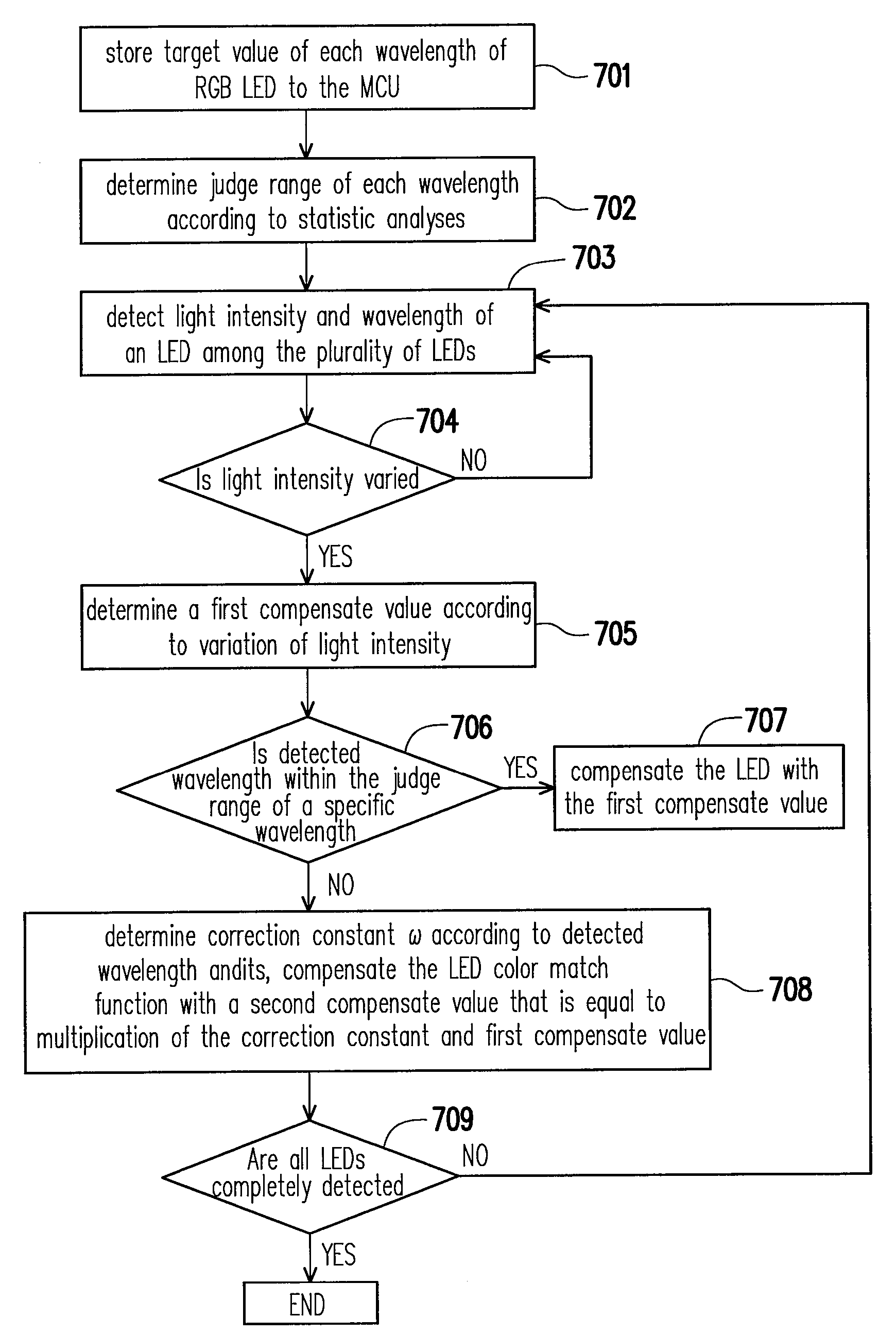
[0029]The invention can be applied to initialize an LED backlight module because same-colour LEDs within a same production batch usually have uniform wavelengths. Moreover, initialization of LED backlight module cannot take only light intensity into account because the wavelength variation causes a shift of its corresponding chromaticity coordinates, i.e. instable colour. FIG. 8 is flowcharts showing a method for initializing wavelength of LED radiation in the LED backlight module. First, in step 801, target values corresponding to wavelengths of each LED in a reference LED backlight module with N LEDs are stored the MCU, wherein N is an integer.

[0030]Then, light intensity and wavelength of an LED in new LED backlight module with N LEDs are detected, as shown in step 802. The process proceeds to judge if there is any variation in light intensity of an LED in the new LED backlight module when compared with its corresponding LED disposed in the same position in th...


PUM


Abstract

The system for stabilizing wavelength of LED (light emitting diode) radiation in backlight module of the LCD (liquid crystal display) comprises two photodiodes, a plurality of LEDs, a microprocessor unit (MCU) and a driver circuit, wherein two photodiodes have different photo sensitivities in response different wavelengths. A target value, associated with a ration of photo sensitivities of the two photodiodes under two different wavelength radiations, is stored to the MCU as a referred value. Thus, another wavelength (or wavelength variation) of LED radiation is derived by comparing another target value with the referred value. The MCU determines a correction constant based on a colour match function of the derived wavelength, and outputs a compensation signal to compensate LED, wherein the compensation signal is equal to multiplication of the correction constant and an original light intensity compensation signal for compensating light intensity loss of the LED.

Description

BACKGROUND OF THE INVENTION[0001]1. Field of the Invention[0002]The present invention generally relates to a method for wavelength stabilization of a liquid crystal display (LCD). More particularly, the present invention relates to a system and method for stabilizing wavelength of LED (light emitting diode) radiation in backlight module of the LCD.[0003]2. Description of Related Art[0004]An LCD includes a controllable transmissive display panel that faces users, and a backlight module that provides the controllable transmissive display panel with illumination from its rear side. The backlight module may employ LED or cold cathode fluorescent lamp (CCFL) as a light source. The LED backlight module has at least two advantages over CCFL backlight module; one is full color reproduction and the other is no contamination of mercury (Hg). During the period of manufacturing the CCFL backlight module, operators may be endangered if mercury contained in the CCFL is released. As such, the LED ...

Claims


Application Information

Patent Timeline
IPC IPC(8): G01J1/20
CPCG09G3/3406G09G2360/145G09G2320/0693G09G2320/0666
Inventor HUANG, ZHI-XIANCAO, HONG-XICHANG, KUN-CHIEHHO, FU-SHUNYANG, CHUN-CHIEH
Owner IND TECH RES INST
Features
  • Generate Ideas
  • Intellectual Property
  • Life Sciences
  • Materials
  • Tech Scout
  • Unparalleled Data Quality
  • Higher Quality Content
  • 60% Fewer Hallucinations
Learn More