Ion implanters

a technology of ion beam and components, which is applied in the field of components of ion beam implanters, can solve the problems of contamination or even damage of the device formed on the substrate, unwanted material may become entrained in the ion beam, and the surface adjacent to the ion beam is the most prone to receiving such deposits

Active Publication Date: 2009-07-02
APPLIED MATERIALS INC
View PDF10 Cites 17 Cited by
  • Summary
  • Abstract
  • Description
  • Claims
  • Application Information

AI Technical Summary

Benefits of technology

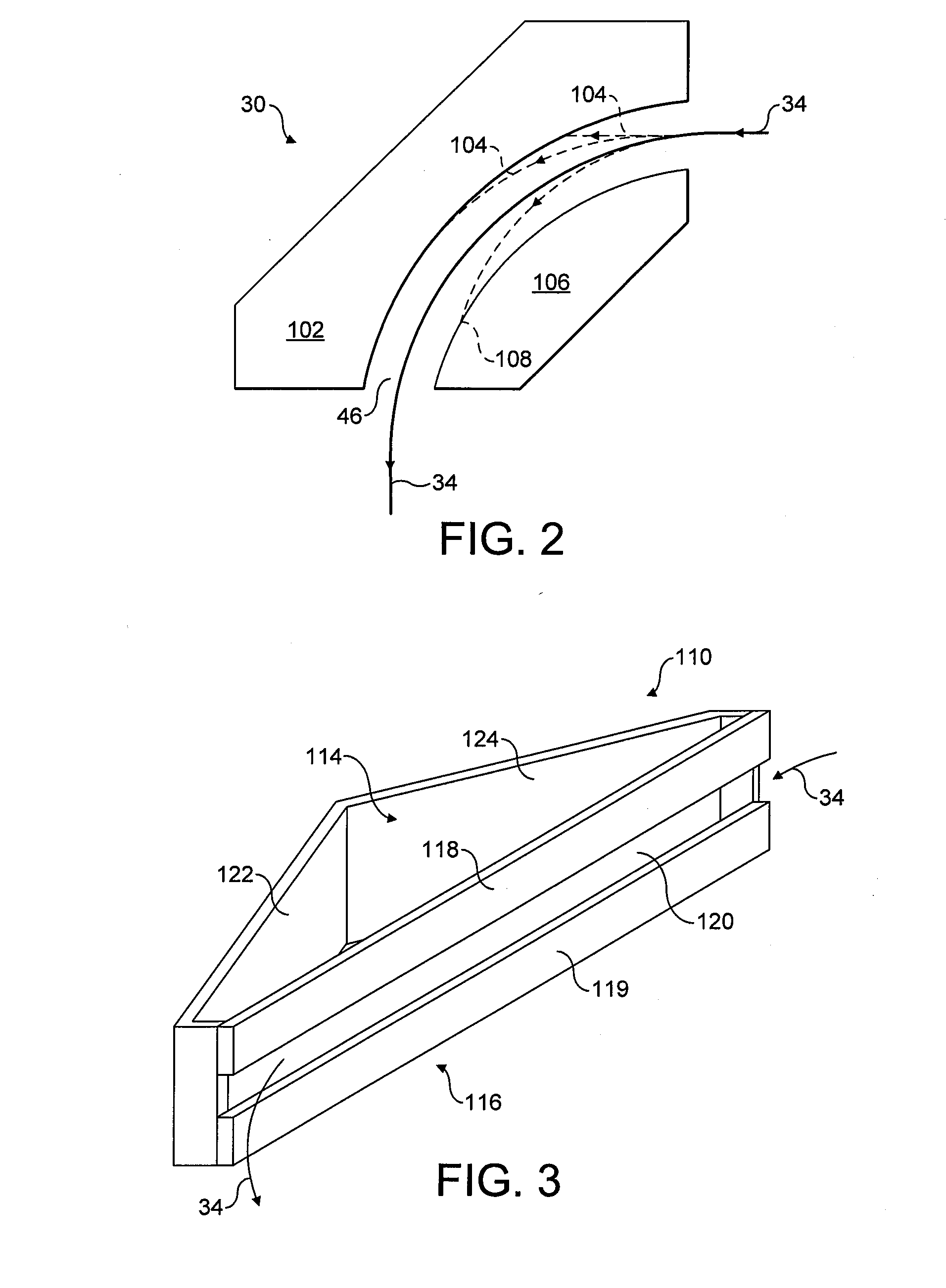
[0027]In any application, the provision of a chamber behind the forward face means that material sputtered from the ions striking a rear face of the chamber is retained within the chamber. Thus, the material does not become entrained within the ion beam and cannot contaminate the substrate.

Problems solved by technology

During normal operation of an ion implanter, unwanted material may become entrained in the ion beam.
This material may strike the substrate causing contamination or even damage to the devices being formed on the substrate.
Surfaces adjacent to the ion beam are most prone to receiving such deposits.
A further problem is the liberation of material from the beamstop when it is struck by the ion beam.
The close proximity of the substrate to the beamstop exacerbates the problem of contamination from the beamstop.

Method used


Image

  • Ion implanters
  • Ion implanters
  • Ion implanters

Examples


Embodiment Construction

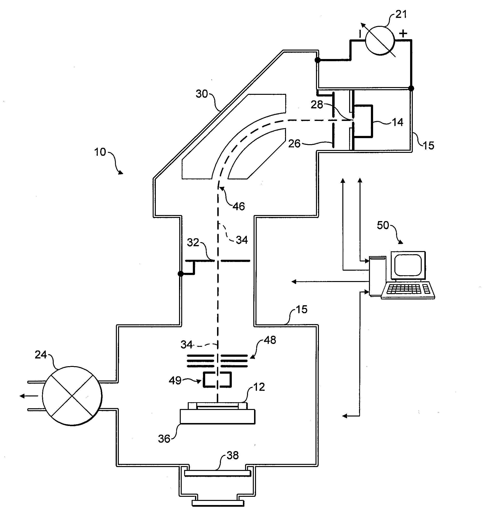
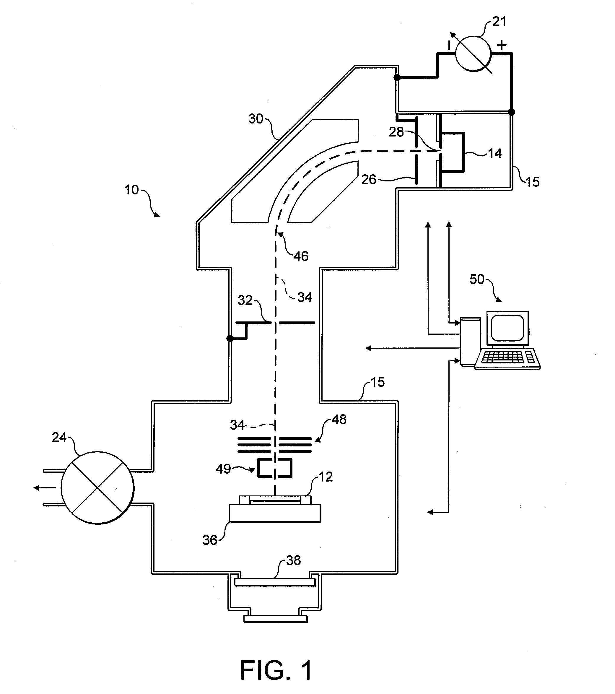
[0040]In order to provide a context for the present invention, an exemplary application is shown in FIG. 1, although it will be appreciated this is merely an example of the application of the present invention and is in no way limiting.

[0041]FIG. 1 shows an ion implanter 10 for implanting ions in semiconductor wafers 12 (or other substrates) that may be used in accordance with the present invention. The ion implanter 10 comprises a vacuum chamber 15 pumped through valve 24. Ions are generated by ion source 14 and are extracted by an extraction lens assembly 26 to form an ion beam 34. In this embodiment the ion beam 34 is steered and shaped through the ion implanter 10 such that the ion beam 34 passes through a mass analysis stage 30. Ions of a desired mass are selected to pass through a mass resolving slit 32 and then conveyed onward along an ion beam path 34 towards the semiconductor wafer 12. In this embodiment, the ions are decelerated before reaching the semiconductor wafer 12 b...


PUM


Abstract

The present invention relates to components in an ion implanter that may see incidence of the ion beam, such as a beam dump or a beam stop. Such components will be prone to the ions sputtering material from their surfaces, and sputtered material may become entrained in the ion beam. This entrained material is a source of contamination. The present invention provides such components with a chamber having an elongate slot opening defined by edges, and operating the ion implanter such that a central portion of the ion beam enters the component through the opening with the edges clipping at least a peripheral portion of the ion beam. The arrangement mitigates the problem of sputtered material escaping back out from the component and becoming entrained in the ion beam.

Description

FIELD OF THE INVENTION[0001]The present invention relates to components in ion implanters having surfaces, such as graphite surfaces, adjacent to the path of the ion beam through the ion implanter. Such surfaces will be prone to sputtering, and sputtered material may become entrained in the ion beam. The present invention primarily addresses this problem of sputtering and entrainment of material.BACKGROUND OF THE INVENTION[0002]Ion implanters are used in the manufacture of semiconductor devices and other materials. In such ion implanters, semiconductor wafers or other substrates are modified by implanting atoms of a desired species into the body of the wafer, for example to form regions of varying conductivity.[0003]Ion implanters are well known and generally conform to a common design as follows. An ion source generally comprises an arc chamber in which a hot plasma is generated. The plasma will contain ions of a desired species to be implanted.[0004]An extraction lens assembly pro...

Claims


Application Information

Patent Timeline
Patent Type & Authority Applications(United States)
IPC IPC(8): G21K5/00
CPCH01J37/05H01J37/3171H01J2237/0213H01J2237/022H01J2237/31705H01J2237/028H01J2237/24405H01J2237/31701H01J2237/0268
Inventor ALCOTT, GREGORY ROBERTMURRELL, ADRIANCASTLE, MATTHEWHILKENE, MARTIN
Owner APPLIED MATERIALS INC
Why Eureka
Try Eureka