
Piezoelectric pump, cooling device, and electronic apparatus

a cooling device and electronic equipment technology, applied in the direction of positive displacement liquid engines, liquid fuel engines, television systems, etc., can solve the problems of reducing the discharge rate and suction rate of the cooling device, the cooling device's natural frequency change, etc., and achieve the effect of excellent connection reliability

Inactive Publication Date: 2009-07-02
SONY CORP
View PDF4 Cites 62 Cited by
  • Summary
  • Abstract
  • Description
  • Claims
  • Application Information

AI Technical Summary

Benefits of technology

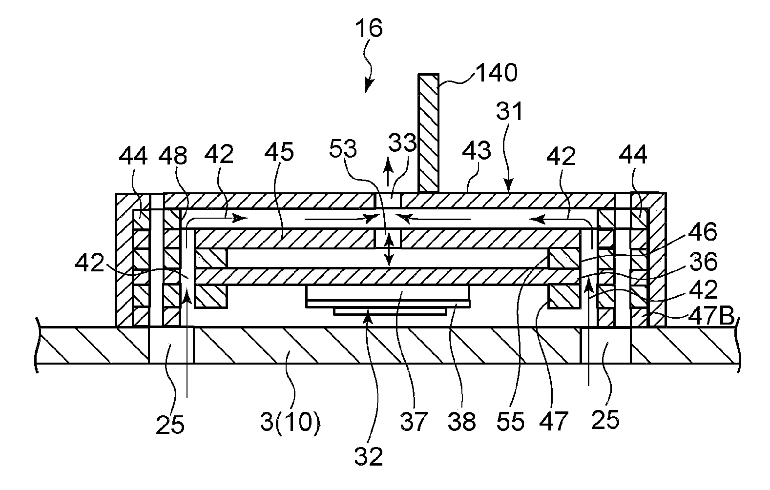
[0010]In the embodiment of the present invention, even if the natural frequency of the piezoelectric body changes, it is possible to detect the signal corresponding to the discharge rate of the fluid from the hole by the detection means and control the drive voltage and drive frequency of the drive unit on the basis of the signal, so that the discharge rate of the fluid from the hole can be controlled at a proper rate (its maximum).
[0012]Thus, it is possible to vary the reactance of the electronic variable reactance element on the basis of the signal corresponding to the discharge rate such that the discharge rate is maximized.
[0019]In the embodiment of the present invention, by adjusting the drive frequency of the piezoelectric body to the natural frequency of a piezoelectric pump corresponding to a position where an object to be cooled is located, the object to be cooled can be selectively and efficiently cooled.
[0022]The piezoelectric pump is used also as a speaker of the electronic apparatus. Thus, the speaker with the excellent reliability of a connection between voltage application wiring and an electrode can be obtained.

Problems solved by technology

However, the cooling device has a property of changing its natural frequency depending on the temperature change of the piezoelectric body.
Therefore, when the drive frequency is fixed as in the past, there is a problem in that the discharge rate and suction rate of the cooling device decrease with the change of an ambient temperature.

Method used


Image

  • Piezoelectric pump, cooling device, and electronic apparatus
  • Piezoelectric pump, cooling device, and electronic apparatus
  • Piezoelectric pump, cooling device, and electronic apparatus

Examples


Embodiment Construction

[0047]Hereinafter, embodiments of the present invention will be described below with reference to the drawings.

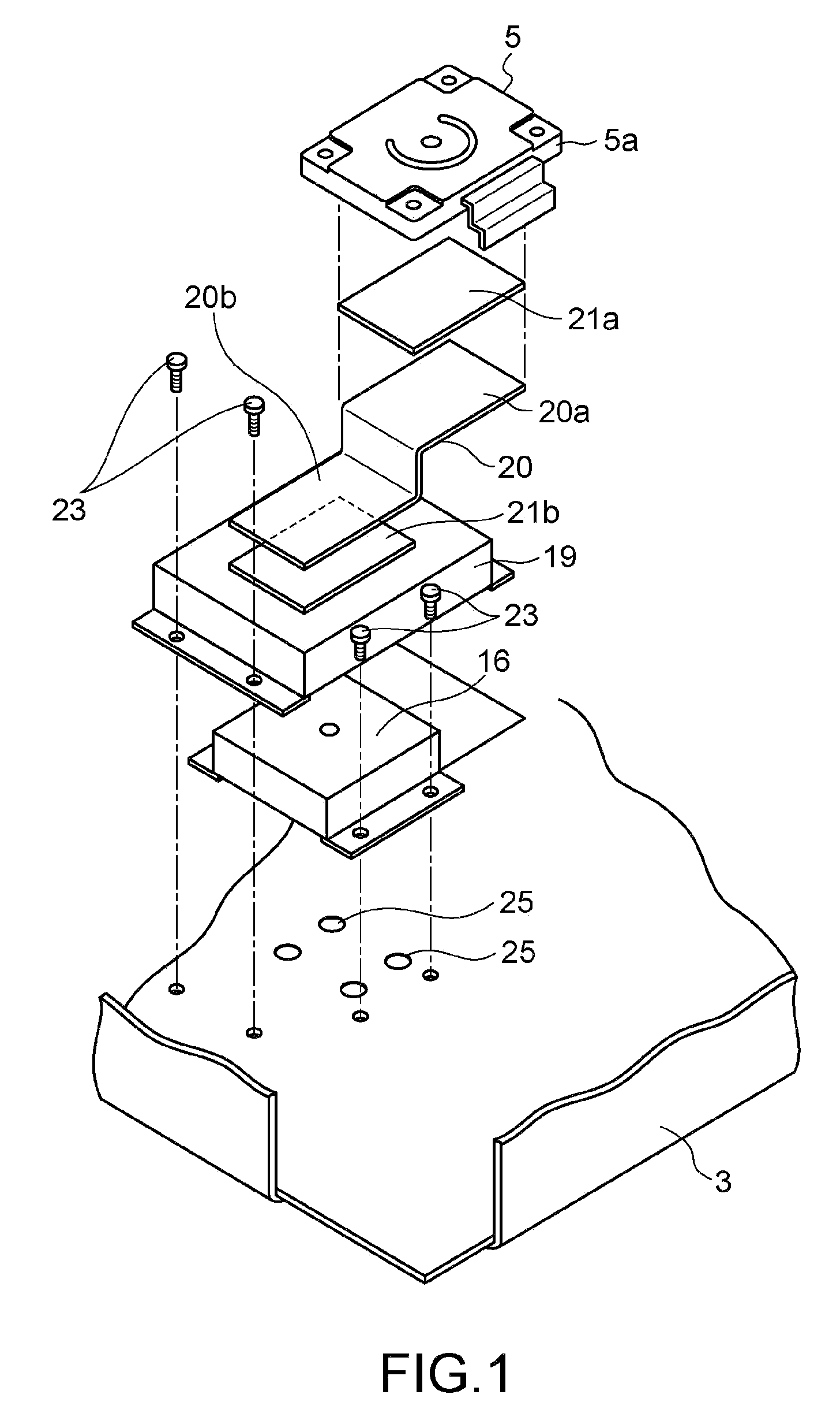
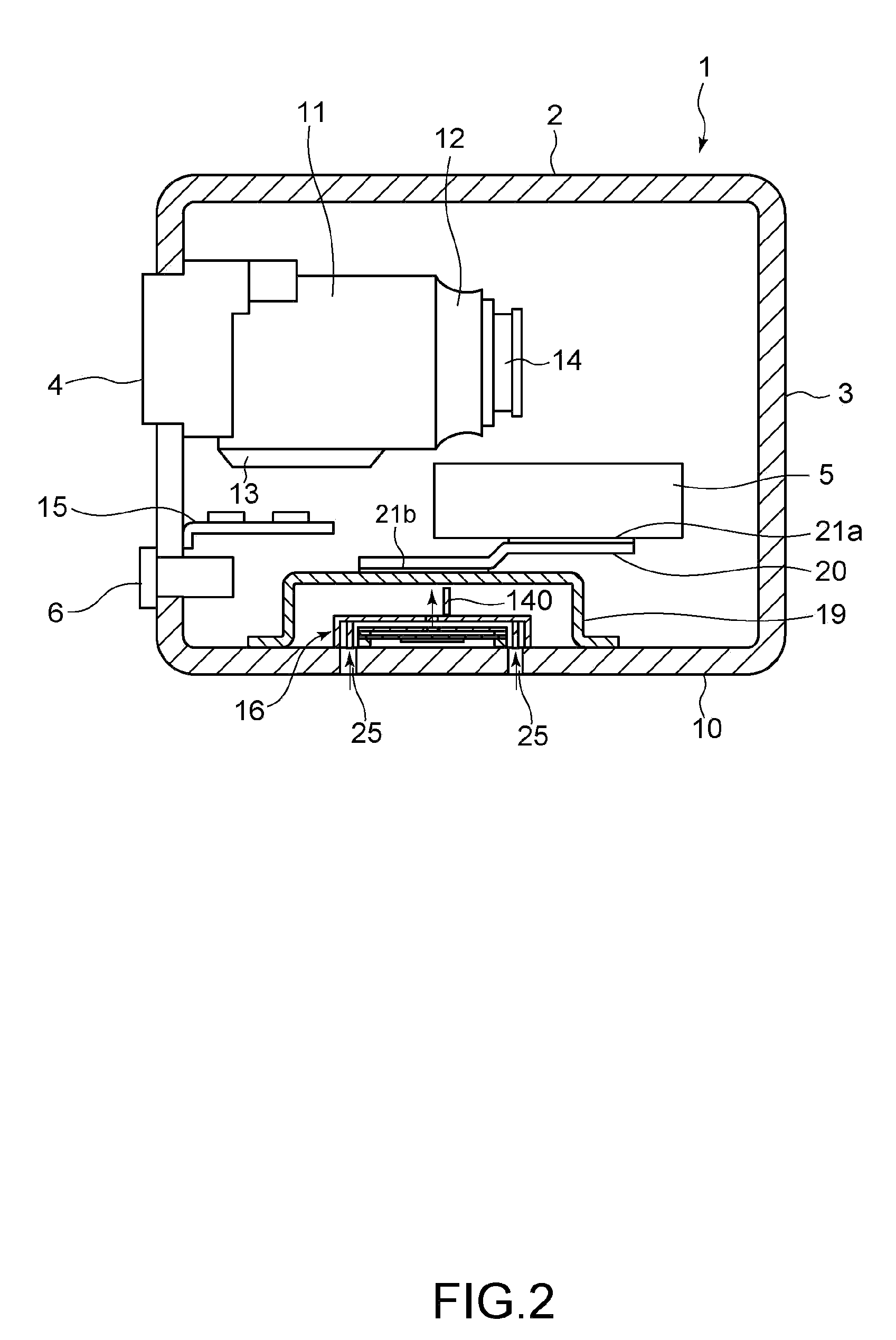
[0048]FIG. 1 is an exploded perspective view of a principal portion showing the constitution of a portable electronic apparatus according to an embodiment of the present invention, FIG. 2 is a sectional view of the portable electronic apparatus including a microphone and a lens, and FIG. 3 is an external view of the electronic apparatus. A portable video camera is taken here for an example of the portable electronic apparatus, but of course a portable phone or other electronic apparatuses are also available.

[0049]As shown in these figures, in a portable video camera 1, a captured subject image is video-recorded / reproduced by an HDD unit 5 mounted in a housing 3 of a camera body 2.

[0050]As shown in FIG. 3, the portable video camera 1 includes a lens 4 of a camera portion, a microphone 6 for collecting sound when an image is captured, a display portion 7 such as an LCD, which...


PUM


Abstract

Disclosed is a piezoelectric pump. The piezoelectric pump includes a pump body, a drive unit, a detection section, and a control unit. The pump body includes a hole for introducing a fluid from outside thereinto and jetting the fluid from inside, a wall portion disposed so as to face the hole, and a piezoelectric body provided on the wall portion to vibrate the wall portion. The drive unit drives the piezoelectric body. The detection section detects a signal corresponding to a discharge rate of the fluid from the hole. The control unit controls a drive voltage and a drive frequency of the drive unit on the basis of the signal.

Description

CROSS REFERENCES TO RELATED APPLICATIONS[0001]The present invention contains subject matter related to Japanese Patent Application JP 2007-336076 filed in the Japanese Patent Office on Dec. 27, 2007, the entire contents of which being incorporated herein by reference.BACKGROUND OF THE INVENTION[0002]1. Field of the Invention[0003]The present invention relates to a piezoelectric pump, a cooling device, and an electronic apparatus used for cooling a hard disk drive or the like mounted in a portable electronic apparatus such as a portable video camera.[0004]2. Description of the Related Art[0005]As a technique for cooling an electronic component mounted in a portable electronic apparatus, there has been disclosed, for example, a “jet generating device” for vibrating a vibration plate which uses a piezoelectric body within a chamber having a nozzle for jetting gas to jet the gas for cooling from the nozzle (see, Japanese Patent Application Laid-open No. 2006-297295 (paragraphs [0029]-[0...

Claims


Application Information

Patent Timeline
IPC IPC(8): H02N2/06F04B17/03H04R17/00
CPCF04B43/046H05K7/20136H04N5/2251G11B33/142H04N23/52
Inventor TOMITA, MINORUSUZUKI, MASAHIROKAYAMA, SHUNSHIMIZU, YUKIKO
Owner SONY CORP
Learn More