Protection device for assembled battery and assembled battery system containing the same

Inactive Publication Date: 2009-07-02
KK TOSHIBA
View PDF21 Cites 20 Cited by
  • Summary
  • Abstract
  • Description
  • Claims
  • Application Information

AI Technical Summary

Benefits of technology

[0011]An object of the present invention is to provide a protection device for an assembled battery having voltage dispersion correcting function of achieving a red

Problems solved by technology

For the assembled battery, dispersion among the battery cells is problematic.
Because the battery cell whose voltage reaches the upper voltage limit is in an over-charged state and the battery cell whose voltage reaches the lower voltage limit is in an over-discharged state, deterioration of battery performance

Method used


Image

  • Protection device for assembled battery and assembled battery system containing the same
  • Protection device for assembled battery and assembled battery system containing the same
  • Protection device for assembled battery and assembled battery system containing the same

Examples


Example

FIRST EMBODIMENT

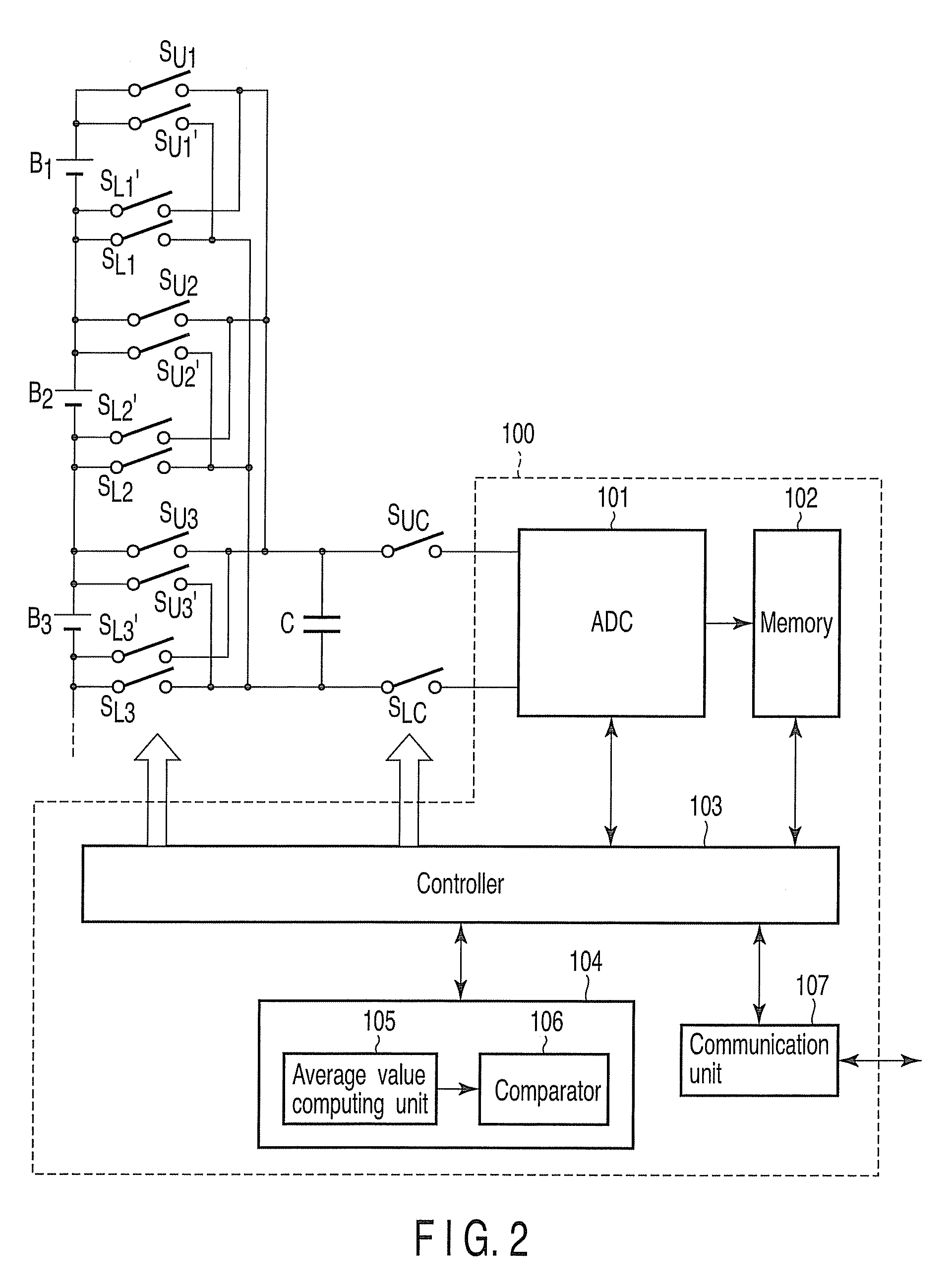
[0031]As shown in FIG. 2, an end of two sampling switches SU1, SU1′, SU2, SU2′ and SU3, SU3′ is connected to a positive terminal of the cell batteries B1, B2 and B3. An end of two sampling switches SL1, SL1′, SL2, SL2′ and SL3, SL3′ is connected to a negative terminal of the cell batteries B1, B2 and B3.

[0032]Although in JP-A 2001-201522 (KOKAI), only sampling switches corresponding to SU1, SU2, SU3 and SL1, SL2, SL3 exist, according to this embodiment, SU1′, SU2′, SU3′ and SL1′, SL2′, SL3′ are added newly. By adding these sampling switches SU1′, SU2′, SU3′ and SL1′, SL2′, SL3′, correction of voltage dispersion of the battery cells B1, B2, and B3 is achieved.

[0033]The voltages of the battery cells B1, B2, and B3 sampled by the newly added sampling switches SU1′, SU2′ and SU3′ and SL1′, SL2′ and SL3′ are sampled by the sampling switches SU1, SU2, SU3 and SL1, SL2, SL3 and then, given to the sampling capacitor C with an reverse polarity to a voltage held on the sampli...

Example

SECOND EMBODIMENT

[0049]As described in the first embodiment, the polarity of the voltage of the sampling capacitor C differs between when the voltage of the battery cell is sampled with the switch Si and when it is sampled with the switch Si′. According to the second embodiment shown in FIG. 5, as well as the transmission switches SUC, SLC placed between an end of the sampling capacitor C and a positive input terminal of the ADC 101 and between the other end of the sampling capacitor C and a negative input terminal of the ADC 101, transmission switches SUC′, SLC′ are added between an end of the sampling capacitor C and the negative input terminal of the ADC 101 and between the other end of the sampling capacitor C and the positive input terminal of the ADC 101.

[0050]By inverting the polarity of input signal of the ADC 101 between when the switch Si is on and when the switch Si′ is on using the transmission switches SUC′, SLC′ added in this way, the polarities of output digital valu...

Example

THIRD EMBODIMENT

[0051]Although in the first and second embodiments, examples using the flying capacitor voltage detection circuit having a sampling capacitor C have been described, the present invention can be applied to the flying capacitor voltage circuit having a plurality of sampling capacitors, which are provided corresponding to each of the battery cells. The third embodiment shown in FIG. 6 shows an example that sampling capacitors C1, C2 are provided corresponding to the battery cells B1, B2.

[0052]Although in the flying capacitor voltage detection circuit having a sampling capacitor as indicated in the first and second embodiments, the voltage of each battery cell is sampled successively one by one, the flying capacitor voltage detection circuit having a plurality of sampling capacitors like this embodiment can sample the voltages of plural battery cells all at once, thereby providing such an advantage that synchronism of voltage detection can be raised.

[0053]FIG. 7 is a ti...


PUM


Abstract

A protection device for an assembled battery includes a sampling capacitor, first switches and second switches to sample the voltages of the battery cells and hold the voltages in the capacitor, a detection unit which detects the voltages of the battery cells based on the voltage sampled by any one of the first switches and the second switches and held on the capacitor and output the detected value, a computing unit which computes an average value of the detected values, a comparator which compares the detected value with the average value so as to obtain a result of comparison indicating a relation in size between the both, and a controller which controls the first switches and the second switches, for the second switches to sample if the detected value obtained by sampling by the first switches is higher than the average value according to the comparison result.

Description

CROSS REFERENCE TO RELATED APPLICATIONS[0001]This is a Continuation Application of PCT Application No. PCT / JP2008 / 065349, filed Aug. 21, 2008, which was published under PCT Article 21 (2) in English.[0002]This application is based upon and claims the benefit of priority from prior Japanese Patent Application No. 2007-218763, filed Aug. 24, 2007, the entire contents of which are incorporated herein by reference.BACKGROUND OF THE INVENTION[0003]1. Field of the Invention[0004]The present invention relates to a protection device for an assembled battery having a function of correcting dispersion of voltage among battery cells and an assembled battery system containing the same.[0005]2. Description of the Related Art[0006]In recent years, an electric vehicle and a hybrid vehicle have been attracting public attention in viewpoints of reduction of environmental load. A vehicle mounted battery which determines the traveling performance of the electric vehicle and the hybrid vehicle is deman...

Claims


Application Information

Patent Timeline
IPC IPC(8): H02J7/00B60L3/00G01R19/00G01R31/36H02J7/02
CPCH02J7/0021H02J7/0016B60L58/22Y02T10/70H02J7/0047H02J7/0019B60L3/0046
Inventor KUROSE, DAISUKEITAKURA, TETSUROTATEBAYASHI, YOSHINAOSHIBUYA, NOBUO
Owner KK TOSHIBA
Why Eureka
Try Eureka