

Liquid discharge head and method of manufacturing the same
a liquid discharge head and liquid discharge technology, applied in the direction of fuel injection apparatus, metal-working apparatus, charge feed systems, etc., can solve the problems of large rate reduction, inability to arrange the discharge ports at high density, fluctuation of the discharge amount of ink liquid droplets, etc., to improve the efficiency of discharging liquid droplets and increase the refill speed
- Summary
- Abstract
- Description
- Claims
- Application Information
AI Technical Summary
Benefits of technology
Problems solved by technology
Method used
Image

Examples
embodiment 1
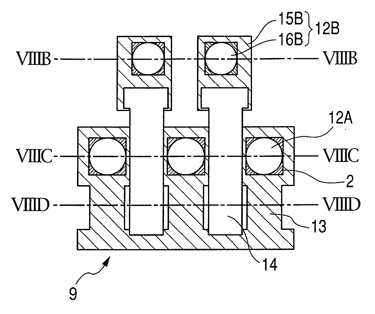
[0064]FIGS. 4A to 4C each illustrate a liquid discharge head according to Embodiment 1 of the present invention. FIG. 4A is a perspective plan view schematically illustrates the liquid discharge head according to this embodiment, FIG. 4B is a cross-sectional view taken along the line IVB-IVB of FIG. 4A, and FIG. 4C is a cross-sectional view taken along the line IVC-IVC of FIG. 4A.
[0065]The liquid discharge head of this embodiment includes a discharge portion 12 communicating with the discharge port 7, a first flow path 13 communicating with discharge portion 12, and a second flow path 14 communicating with discharge portion 12. The first flow path 13 and the second flow path 14 are provided with respect to one discharge portion 12 (a space for accommodating each energy generating element 2), and a first flow path 13 and a second flow path 14 each communicating with the discharge portion. The first flow path 13 extends from the supply opening 9 (see FIG. 2H) to the discharge portion ...
embodiment 2
[0070]FIGS. 5A to 5C each illustrate a liquid discharge head according to Embodiment 2 of the present invention. FIG. 5A is a perspective plan view schematically shows the liquid discharge head according to this embodiment, FIG. 5B is a cross-sectional view taken along the line VB-VB of FIG. 5A, and FIG. 5C is a cross-sectional view taken along the line VC-VC of FIG. 5A.
[0071]This embodiment is different from Embodiment 1 in that the second flow path 14 further communicates with the adjacent discharge portions 12 as well. Except for the above difference, the same arrangement as embodiment 1 is employed in embodiment 2. The liquid discharge head structured as described above operates similarly to the liquid discharge head of Embodiment 1 and produces the similar effect. The inventors consider that, in particular, when some of the discharge ports 7 of every several discharge ports 7 simultaneously discharge liquids, the discharge portions 12 corresponding to those discharge port 7 dis...
embodiment 3
[0072]FIGS. 6A to 6C each illustrate a liquid discharge head according to Embodiment 3 of the present invention. FIG. 6A is a perspective plan view schematically shows the liquid discharge head according to this embodiment, FIG. 6B is a cross-sectional view taken along the line VIB-VIB of FIG. 6A, and FIG. 6C is a cross-sectional view taken along the line VIC-VIC of FIG. 6A.
[0073]This embodiment is different from Embodiment 1 in that the second flow path 14 is connected to each of the discharge portions 12 through a flow path wall formed between the adjacent discharge portions 12 and between the adjacent first flow paths 13. Except for the above difference, embodiment 3 employs the same arrangement as embodiment 1. The second flow path 14 accesses the discharge portion 12 from downstream of the liquid supply direction (a direction from the supply opening toward the energy generating element) in the first flow path 13. Unlike in Embodiment 1, the second flow path 14 is not provided a...
PUM
| Property | Measurement | Unit |
|---|---|---|
| Nanoscale particle size | aaaaa | aaaaa |
| Flow rate | aaaaa | aaaaa |
| Area | aaaaa | aaaaa |
Abstract
Description
Claims
Application Information