
Safety syringe, syringe plunger processing system and method

a technology of safety syringes and processing systems, which is applied in the field of safety syringes, can solve the problems of easy breakage of the syringe shank and the inside of the barrel of the plunger, so as to save time and labor, prevent illegal collection and recycling, and simplify the fabrication of safety syringes

Inactive Publication Date: 2009-07-02
WANG SHEEI JIN
View PDF0 Cites 34 Cited by
  • Summary
  • Abstract
  • Description
  • Claims
  • Application Information

AI Technical Summary

Benefits of technology

[0006]The present invention has been accomplished under the circumstances in view. It is therefore the main object of the present invention to provide a safety syringe, which is self-destructive to prevent illegal collecting and recycling and accidental injury. It is another object of the present invention to provide a safety syringe fabrication method, which simplifies the fabrication of safety syringes, saving much time and labor and effectively lower the cost. To achieve these and other objects of the present invention, the safety syringe comprises a barrel, a needle assembly and a plunger. The plunger comprises a shank, a connector at the front side of the shank, and a metal hook bonded to the connector for hooking the needle assembly so that the needle assembly can be pulled backwards and received inside the barrel after the service of the safety syringe. The shank has a breaking neck through which the shank can easily be broken after the use of the safety syringe, leaving the broken front part of the plunger inside the barrel.

Problems solved by technology

The shank has a breaking neck through which the shank can easily be broken after the use of the safety syringe, leaving the broken front part of the plunger inside the barrel.

Method used


Image

  • Safety syringe, syringe plunger processing system and method
  • Safety syringe, syringe plunger processing system and method
  • Safety syringe, syringe plunger processing system and method

Examples


Embodiment Construction

[0018]Referring to FIGS. 3˜6, a safety syringe in accordance with the present invention is shown comprised of a plunger 2, a needle assembly 3, a barrel 4 and a protective cap 5.

[0019]The plunger 2 comprises a metal hook 21, a connector 22, a shank 23, a thumb rest 24 and a rubber stopper 25. The metal hook 21 has a front end biased at an angle and terminating in a front U-turn 211 and then a hook tip 212. A bottom end of the metal hook 21 is fixedly fastened to the connector 22. The connector 22 comprises an insertion hole 2211 axially extending to the front end, a reduced diameter portion 221, a locating groove 2212 extending around the periphery of the reduced diameter portion 221, and at least one locating flange 2213 extending around the periphery of the locating groove 2212. The bottom end of the metal hook 21 is inserted into the insertion hole 2211 of the connector 22. After insertion of the bottom end of the metal hook 21 into the insertion hole 2211 of the connector 2, the...


PUM

PropertyMeasurementUnit
Lengthaaaaaaaaaa
Diameteraaaaaaaaaa
Frequencyaaaaaaaaaa

Abstract

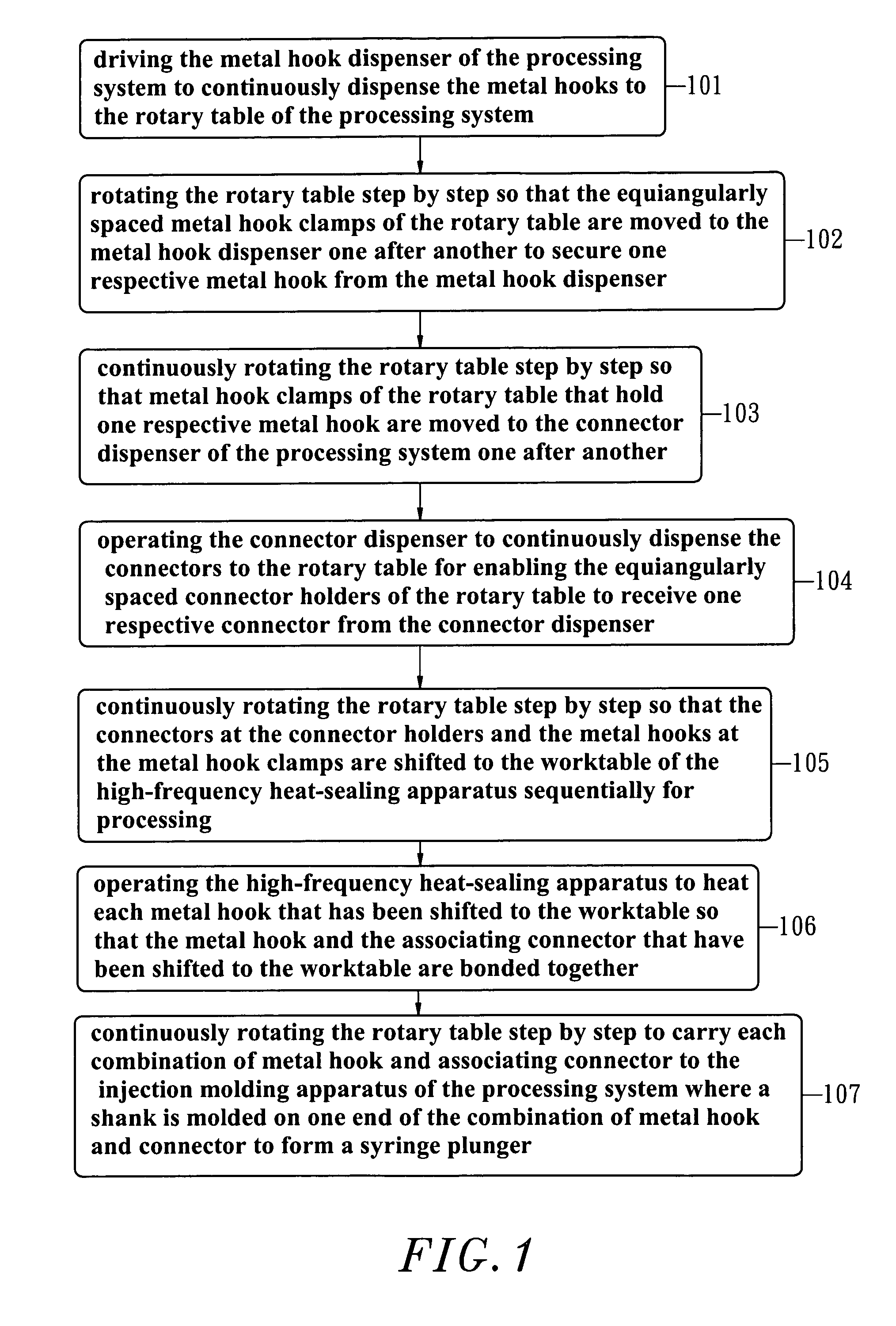
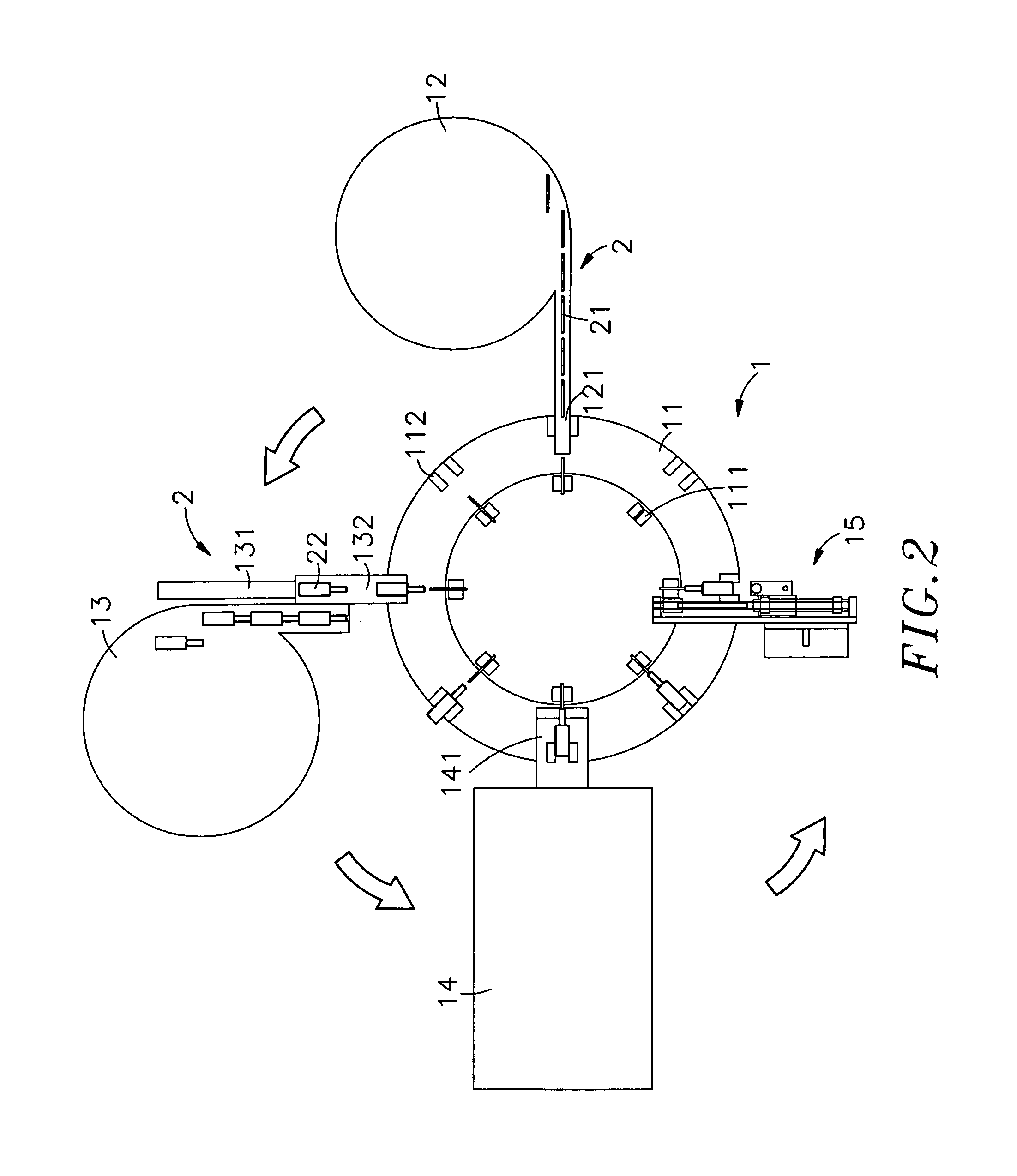
A safety syringe includes a plunger for moving a rubber stopper in a barrel to force the medicine out of a needle assembly into the patient's body that has a connector at the front side of a shank thereof to hold a metal hook for hooking the needle assembly so that the needle assembly can be pulled backwards and received inside the barrel after the service of the safety syringe. The invention relates also automatic fabrication of the plunger through a syringe plunger processing system that comprises a metal hook dispenser for dispensing metal hooks, a connector dispenser for dispensing connectors, a high-frequency heat-sealing apparatus for bonding each metal hook to one respective connector, and an injection molding apparatus for molding a shank on each combination of metal hook and connector.

Description

BACKGROUND OF THE INVENTION[0001]1. Field of the Invention[0002]The present invention relates to a hypodermic syringes and more particularly, to a safety syringe of which a plunger comprises a shank, a connector at the front end of the shank, and a metal hook affixed to the connector for hooking a needle assembly for enabling the needle assembly to be received inside a barrel after the service of the safety syringe. The invention relates also to the fabrication of the plunger.[0003]2. Description of the Related Art[0004]If a syringe is repeatedly used, disease infection will happen on the patient. Therefore, disposable syringes are commonly used for clinical application. An ordinary disposable syringe essentially comprises a barrel, a plunger having a rubber plunger head and a needle assembly. During use, the plunger is pushed forwards, causing the rubber plunger head to squeeze medicine out of the barrel through a needle at a needle hub of the needle assembly into the body of the p...

Claims


Application Information

Patent Timeline
IPC IPC(8): A61M5/50B29C45/00
CPCA61M5/3202A61M5/322A61M2005/31506B29C45/14A61M2005/323A61M2005/5073A61M2005/3224
Inventor WANG, SHEEI-JIN
Owner WANG SHEEI JIN
Learn More