Condenser and metering device in refrigeration system for saving energy

a technology of refrigeration system and condenser, which is applied in the field of refrigeration system, can solve the problems of low system capacity, large space occupation of water-cooled condensers, and inability to meet the needs of the public, and achieves the effects of low production cost, low production cost and high cooling capacity

Inactive Publication Date: 2009-07-09
SU KUOJUI +1
View PDF11 Cites 6 Cited by
  • Summary
  • Abstract
  • Description
  • Claims
  • Application Information

AI Technical Summary

Benefits of technology

[0008]The present invention addresses the problem by designing a new type of condenser named ES condenser. The ES condenser is modeled after a water-cooled condenser but is much smaller in size and less expensive to make. This new type of condenser makes it possible to manufacture small or medium size water-cooled refrigeration system that have high cooling capacity and at the same time are energy efficient and affordable to the public.
[0009]The present invention addresses the above problem by use of a new type of metering device named pump valve which utilizes the electricity power to pump refrigerant liquid from the condenser to the evaporator to prevent the evaporator from being starved when the condenser gets too cold in cold weather and the head pressure too low. The new metering device allows the refrigeration system to operate at its maximum cooling capacity in cold weather without having to sacrifice the system capacity.
[0010]A refrigeration system that utilizes the Energy Saving arrangement will be able to achieve high cooling capacity and high energy efficiency and at the same time keep the system at an affordable price to the consumer.

Problems solved by technology

Unfortunately, the conventional water-cooled condenser is designed with a water cooling tower to cool the water for cooling the condenser.
This type of water-cooled condenser occupies a lot of space and is too expensive to be accepted widely by the public consumer.
The result of the evaporator being starved is lower system capacity.
Unfortunately this means that the conventional refrigeration system cannot be as energy efficient as desired in cold weather due to the necessity of keeping the system capacity at a sufficient level.

Method used


Image

  • Condenser and metering device in refrigeration system for saving energy
  • Condenser and metering device in refrigeration system for saving energy
  • Condenser and metering device in refrigeration system for saving energy

Examples


Embodiment Construction

[0044]The apparatuses and methods for saving energy in a refrigeration system such as air conditioner, freezer or refrigerator system, in accordance with the present invention will be explained in the following drawings.

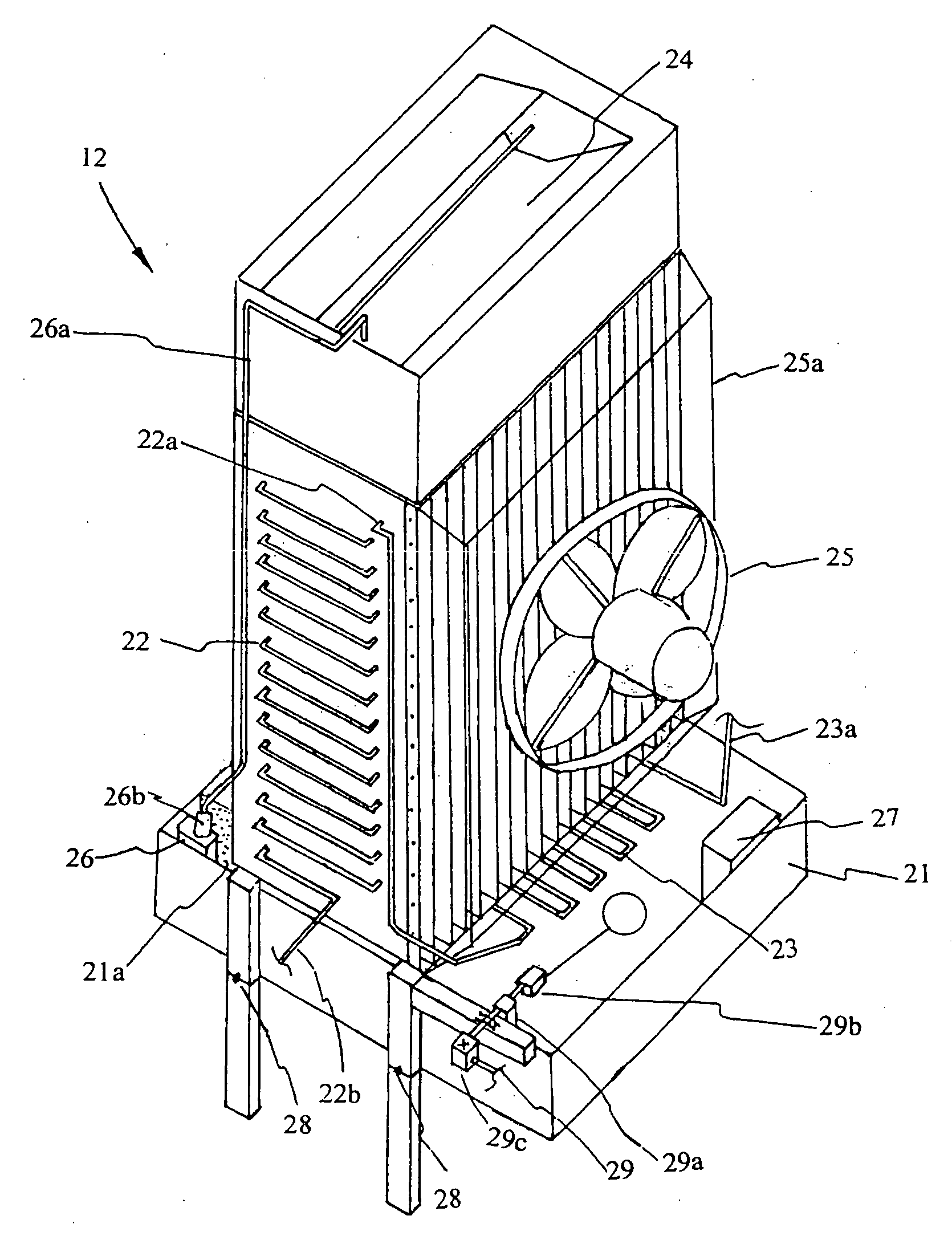
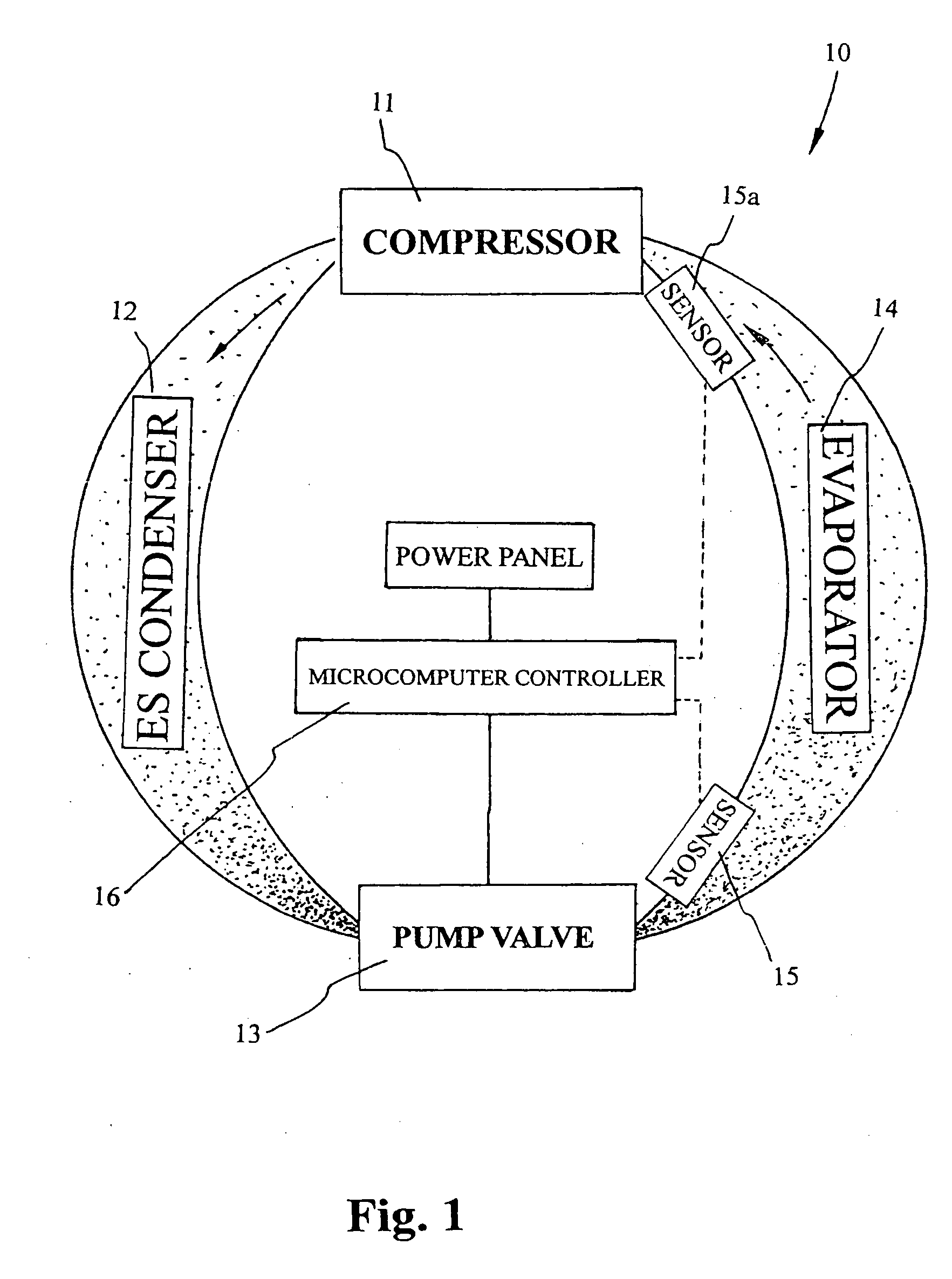
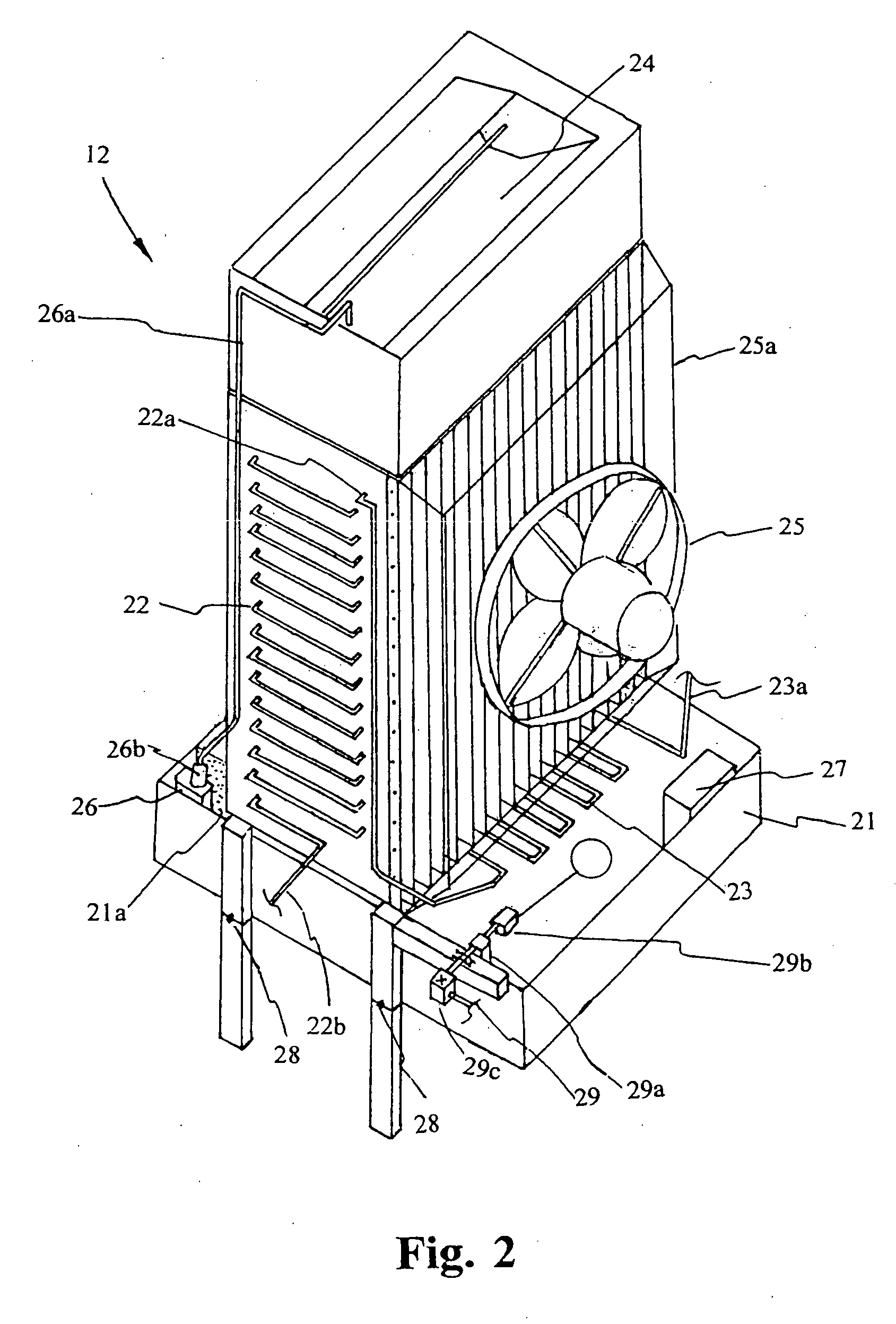
[0045]Referring to FIG. 1 of the drawings, a refrigeration system according to a preferred embodiment is illustrated, wherein the refrigeration system comprises a compressor 11, a condensing unit 12, an evaporator 14, and an energy saving arrangement which comprises a water-cooling device and a metering device which is a refrigerant liquid pump. Accordingly, the compressor 11, which is a conventional type of compressor, compresses the less dense refrigerant gas / vapor (the less dark portion of the evaporator) coming out of the evaporator 14. The compressed hot refrigerant gas gets cooled down and is condensed as it passes through the condensing unit 12 and becomes refrigerant liquid (darker portion inside the condenser). The metering device comprises a pump valve 13 f...


PUM


Abstract

A refrigeration system includes an evaporator, a compressor compressing a refrigerant coming out of the evaporator, a condensing unit which includes a finned tube guiding the refrigerant from the compressor back to the evaporator; and an energy saving arrangement. The energy saving arrangement includes a water-cooling device frequently introducing a predetermined amount of water to a surface of the finned tube to water-cool the refrigerant within the finned tube for enhancing a cooling efficiency of the condensing unit while being energy efficient. The energy saving arrangement further includes a metering device for controllably pumping the refrigerant from the condensing unit to the evaporator especially when a pressure inside the condensing unit is lower than a threshold pressure.

Description

CROSS REFERENCE OF RELATED APPLICATION[0001]This is a non-provisional application of a provisional application having an application No. 61 / 010,018 and a filing date of Apr. 4, 2008.BACKGROUND OF THE PRESENT INVENTION[0002]1. Field of Invention[0003]The present invention relates the refrigeration system, and more particularly to a condenser and a metering device incorporated in the refrigeration system to enhance the efficiency thereof and to save energy.[0004]2. Description of Related Arts[0005]A typical refrigeration system, such as an air conditioner (cooling), a freezer or a refrigerator, includes four main components: a compressor, a condenser, a metering device, and an evaporator. The compressor compresses the gas refrigerant from the evaporator into the condenser. The condenser, which is installed outside the room, ejects the heat out of the gas refrigerant and condenses the gas refrigerant, turning gas into liquid refrigerant. The metering device controls the amount of liqui...

Claims


Application Information

Patent Timeline
Patent Type & Authority Applications(United States)
IPC IPC(8): F25D15/00F25B39/04F25B39/00F25B39/02G05D7/06
CPCF25B39/04F25B2339/047F25B2339/041
Inventor SU, KUOJUISU, LING JU
Owner SU KUOJUI
Why Eureka
Try Eureka