
Method for operating a spark ignition engine

a technology of spark ignition and engine, which is applied in the direction of machines/engines, output power, electric control, etc., can solve the problems of high level of pollutant emissions, in particular soot emissions in the full load operating mode, and inability to operate spark ignition engines. to achieve the effect of reducing temperature level, adequate power level and increasing thermodynamic efficiency

Active Publication Date: 2009-07-09
DAIMLER AG
View PDF5 Cites 13 Cited by
  • Summary
  • Abstract
  • Description
  • Claims
  • Application Information

AI Technical Summary

Benefits of technology

[0010]In a method for operating a spark ignition engine, wherein the inlet valves of the spark ignition engine are closed very early or very late, and a combustion air flow which is supplied to the spark ignition engine is compressed by means of a charger, and, under full load operation, the inlet valves are closed either early or late to avoid knocking of the engine, a partial flow of re-circulated exhaust gas is supplied to the combustion air flow supplied to the engine also during full load engine operation.
[0011]The very early or very late closing of the at least one inlet valve, in particular in conjunction with a geometric compression ratio which is increased compared to the operating mode of a normal supercharged engine, causes a reduction in the temperature level accompanied by increased thermodynamic efficiency. The filling of the cylinders which is reduced by the closing times of the inlet valves is at least approximately compensated for by the compression of the combustion air flow by means of the charger, with the result that an adequate power level is available. A single-stage or multi-stage charger in the form of a turbocharger, compressor or the like, if appropriate in combination with an electric booster or the like, can be used as the charger. At least at full load, a partial flow of exhaust gas is re-circulated to the intake duct as a further measure for reducing the temperature.
[0012]The sum of the abovementioned measures permits full use of potential advantages under full load and high partial load engine operation: The temperature level is lowered to such an extent that there is no need for enriching the fuel / air mixture. According to the invention, the spark ignition engine can be operated at least at full load and in particular also at partial load with an air ratio of greater than or equal to approximately 1, and advantageously with an air ratio in a range from approximately 1 to approximately 2. By avoiding thermal-mechanical overloading, a low specific level of fuel consumption with virtually soot-free exhaust gas is obtained at full load and at partial load. The exhaust gas may be further treated by a catalytic converter of any design arranged in the exhaust duct.
[0014]In one expedient embodiment, the at least one inlet valve of a particular or each cylinder is closed timely before the bottom dead center (540° crank angle) which is associated with the intake stroke. The closing preferably takes place at a crank angle in a range of 80° to 60° and in particular at approximately 70° before the associated dead center. This provides for an optimum combination of the power which can be produced and the lowest fuel consumption.

Problems solved by technology

However, the injection systems of the diesel engines and other components are expensive.
Furthermore, their high level of pollutant emissions, in particular soot emissions in the full load operating mode, is also disadvantageous.
However, the operating efficiency of spark ignition engines is limited by a large number of thermodynamic peripheral conditions.
The thermodynamic efficiency is correspondingly limited.
As a result, the respective cylinder is only filled incompletely.
The pistons and components which conduct exhaust gas in the region of the outlet valves are subject to high thermal loading.
In order to reduce the thermal loading, enrichment of the fuel / air mixture is usually performed in the full load operating mode, which leads to disadvantages in terms of fuel consumption and increased emissions of pollutants.
In particular in view of the last-mentioned disadvantages, spark ignition engines which are operated in this way are suitable for utility vehicles only to a limited extent.
The usual thermal limiting through enrichment of the fuel / air mixture at full load leads, particularly in utility vehicles with high full load operating periods, results in inadequate operating efficiency so that the potential for low emissions of pollutants is not utilized.

Method used


Image

  • Method for operating a spark ignition engine
  • Method for operating a spark ignition engine

Examples


Embodiment Construction

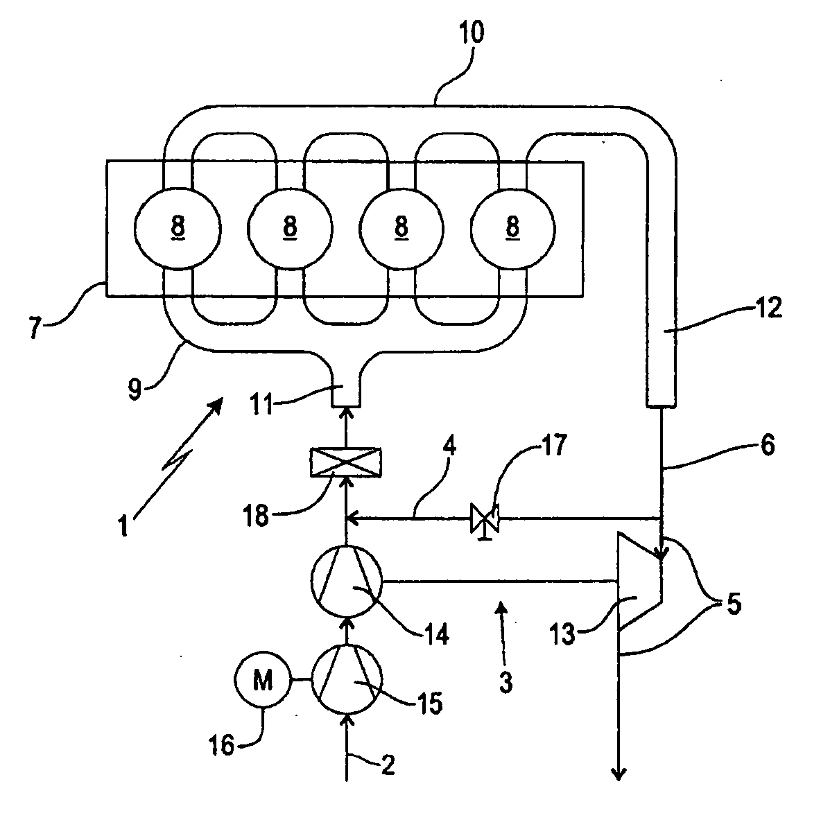
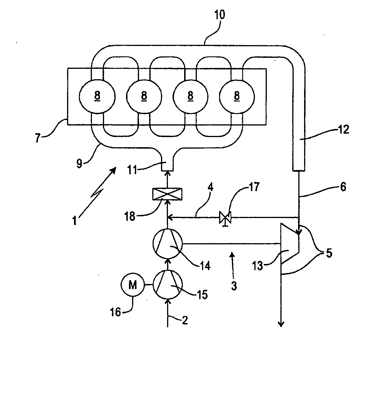
[0018]The FIGURE shows schematically a spark ignition engine 1 in including cylinder block 7 with four cylinders 8 in which pistons which are arranged in such a way that they can move up and down are disposed.

[0019]As illustrated an intake duct 11 supplies a combustion air flow 2 including a portion of recirculated exhaust gas to the cylinders 8 via an intake manifold 9. In order to form a fuel / air mixture which is to be burnt in the cylinders 8, fuel can either be injected into the intake duct 11 (intake manifold injection) or directly into the cylinders 8 (direct injection). The supply of the combustion air flow 2 to the cylinders 8 is controlled by means of inlet valves (not illustrated), wherein each cylinder 8 has at least one inlet valve.

[0020]The exhaust gases which are produced during the combustion of the fuel / air mixture in the cylinders 8 are conducted away as exhaust gas flow 6 from the cylinders 8 via an exhaust gas manifold 10 and an exhaust line 12. The outlet control...


PUM


Abstract

In a method for operating a spark ignition engine, wherein the inlet valves of the spark ignition engine are closed very early or very late, and a combustion air flow which is supplied to the spark ignition engine is compressed by means of a charger, and, under full load operation, the inlet valves are closed either early or late to avoid knocking of the engine, a partial flow of re-circulated exhaust gas is supplied to the combustion air flow supplied to the engine also during full load engine operation.

Description

[0001]This is a Continuous-In-Part Application of pending international patent application PCT / EP2007 / 005804 filed Jun. 29, 2007 and claiming the priority of German patent application 10 2006 032 719.5 filed Jul. 14, 2006.BACKGROUND OF THE INVENTION[0002]The invention relates to a method for operating a spark ignition engine, in particular in a utility vehicle wherein at least one inlet valve is closed very late or very early and air compressed by a charger is supplied to the engine.[0003]Usually diesel engines are used in utility vehicles, which, depending on the design with high compression ratios providing for a comparatively high thermodynamic efficiency level have generally a good operating efficiency. However, the injection systems of the diesel engines and other components are expensive. Furthermore, their high level of pollutant emissions, in particular soot emissions in the full load operating mode, is also disadvantageous.[0004]Spark ignition engines can be used, given a c...

Claims


Application Information

Patent Timeline
Patent Type & Authority Applications(United States)
IPC IPC(8): F02M25/07
CPCF02B29/0406F01L2820/01F02B37/18F02B47/08F02B2275/32F02D13/0234F02D13/0269F02D41/0007F02D41/0065F02D2041/001F02M25/0711F02M25/0726Y02T10/144Y02T10/142Y02T10/47F02B37/013F02M26/08F02M26/22Y02T10/12Y02T10/40
Inventor KOCH, THOMAS
Owner DAIMLER AG
Learn More