Solar collector desiccant system

a technology of desiccant system and solar collector, which is applied in the safety of solar heat collectors, separation processes, lighting and heating apparatus, etc., can solve the problems of affecting the efficiency of the system, so as to achieve the effect of increasing the surface area

Inactive Publication Date: 2009-07-09
SOLFOCUS
View PDF8 Cites 35 Cited by
  • Summary
  • Abstract
  • Description
  • Claims
  • Application Information

AI Technical Summary

Benefits of technology

[0006]The present invention is a desiccant system for controlling moisture in a solar collector. The desiccant system has a desiccant bed enclosed within a housing, and is thermally coupled to the solar collector as well as being fluidly coupled to it through an orifice. Waste heat from the solar collector is conducted to the desiccant system and is used to regenerate the des

Problems solved by technology

While flat panels incorporate very little or no air space within their systems, solar concentrators may contain a significant amount of air space due to the presence of optical elements which are used to concentrate light.
Because solar concentrator systems focus light onto a small area, even a slight deviation in optical accuracy can greatly affect the efficiency of the system.
Moisture within a solar collector can result in other problems, such as diffusion into semiconductor devices

Method used


Image

  • Solar collector desiccant system
  • Solar collector desiccant system
  • Solar collector desiccant system

Examples


Embodiment Construction

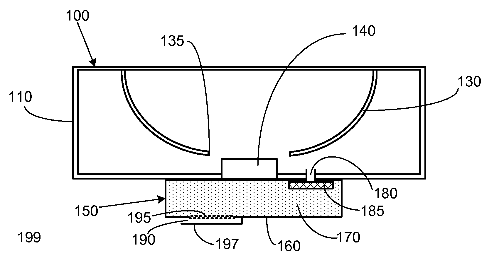
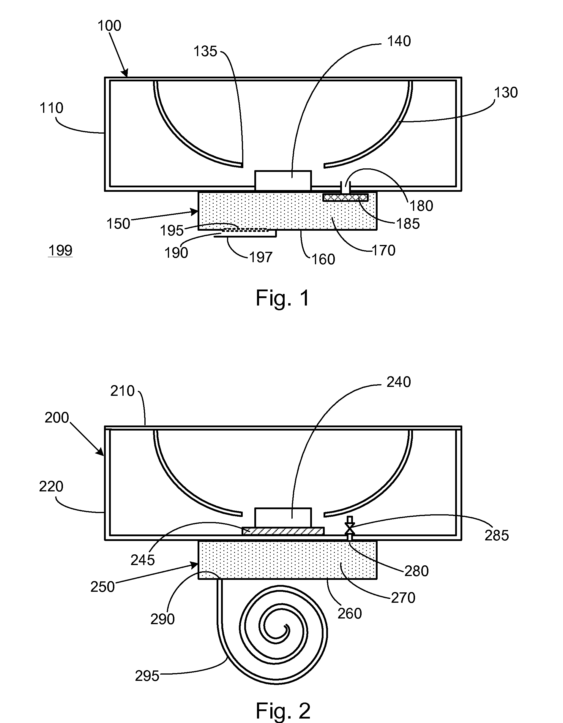
[0013]In the cross-sectional view of FIG. 1, a first embodiment of the present invention includes a solar collector 100 and a desiccant system 150. Solar collector 100, which is a general representation of solar collector, includes an enclosure 110, an optical element 130, and a receiver 140. Receiver 140 includes a photovoltaic cell and associated components critical for operation of the photovoltaic cell, such as an electrical circuit board and an electrically insulating base. Optical element 130 is depicted in FIG. 1 as a concave mirror with a central opening 135. However, optical element 130 is merely representative of one or more optics which may be utilized in a solar collector such as Fresnel lenses, convex mirrors, planar reflectors, optical prisms, parabolic troughs, and the like.

[0014]To control the moisture content of air within enclosure 110, solar collector 100 is coupled to a desiccant system 150. Desiccant system 150 includes a housing 160, a desiccant bed 170 contain...


PUM

PropertyMeasurementUnit
Temperatureaaaaaaaaaa
Volumeaaaaaaaaaa
Electrical conductoraaaaaaaaaa

Abstract

The present invention is a desiccant system for controlling moisture in a solar collector. The desiccant system has a desiccant bed enclosed within a housing, and is thermally coupled to the solar collector as well as being fluidly coupled to it through an orifice. Waste heat from the solar collector is conducted to the desiccant system and is used to regenerate the desiccant bed. The desiccant system includes moisture barriers which cause moisture from the desiccant to preferentially be released to the external environment rather than entering the solar collector.

Description

RELATED APPLICATIONS[0001]This application claims priority to U.S. Provisional Patent Application Ser. No. 61 / 019,586 filed on Jan. 7, 2008 entitled “Solar Collector Desiccant System,” which is hereby incorporated by reference as if set forth in full in this application for all purposes.BACKGROUND OF THE INVENTION[0002]As the demand for solar energy continues to increase as a source of renewable energy, solar collectors must be designed to operate under the wide range of climate conditions which may be encountered worldwide. In one aspect of environmental conditions, solar collectors must be able to withstand exposure to moisture, such as rain, high humidity in tropical zones, and condensation in cold climates.[0003]Solar collectors can be generally categorized into two types, flat panel technology and solar concentrators. Flat panels are large arrays of photovoltaic cells in which solar radiation impinges directly on the cells. In contrast, solar concentrators utilize optical eleme...

Claims


Application Information

Patent Timeline
IPC IPC(8): F24J2/46B01D53/04H01L31/058
CPCB01D53/261B01D2253/10B01D2259/40098H01L31/0547F24J2/4618Y02E10/40Y02E10/52F24J2/4612F24S40/40F24S40/42
Inventor SPENCER, MARKASKINS, STEPHEN
Owner SOLFOCUS
Why Eureka
Try Eureka