Rocket-powered kite plane for gentle climb and acceleration to extreme staging altitudes

a kite plane and kite technology, applied in space shuttles, transportation and packaging, space vehicles, etc., can solve the problems of reducing rocket propulsion efficiency, requiring extra propellants, and compromising aerodynamic efficiency, so as to reduce aerodynamic loads, enhance flight ability, and reduce mass.

Inactive Publication Date: 2009-07-09
CORMIER LEONARD N
View PDF8 Cites 18 Cited by
  • Summary
  • Abstract
  • Description
  • Claims
  • Application Information

AI Technical Summary

Benefits of technology

[0004]Rocket power in combination with large wings allows lifting flight at much higher altitude than previous approaches. The volume within the relatively large wings provides sufficient space for the large amount of propellants required by the rocket engine and obviates or at least drastically reduces the need for fuel tanks outside of the airfoil surfaces that compromise aerodynamic efficiency. The rapid expenditure of the propellants enhances the ability for flight at greatly reduced mass at extreme altitudes where rocket propulsion performs well. Climb and acceleration at the relatively slow speed required by this approach results in a potential for the use of airfoil surfaces formed from very lightweight skin panels and lightweight truss structures which make large wings practical. While this approach tends to require more propellant than other approaches to reach equivalent energy levels, the disadvantages of requiring extra propellants are small, while the advantages of the gentle flight to these levels are large, and include the ability to construct the vehicle with many off-the-shelf components and a minimum amount of exotic and expensive materials. The most likely application of this approach is for the first stage, also called the carrier, of a two-stage-to-orbit space transport. This, in turn, permits staging of a TSTO space transport at extreme altitudes. We define our term “rocket-powered kite plane” to be an aircraft as described above, that uses a high ratio of wing area to system mass in combination with rocket power to reach extreme altitude, and, in some embodiments, high speed, in a manner that sharply reduces aerodynamic loads due to high dynamic pressures and mismatches of aerodynamic and inertial loads to permit the use of ultralight-type aircraft components.
[0005]Ultralight structures require constraining dynamic pressures during ascent and acceleration, which is generally inefficient for rocket propulsion. However, this inefficiency is more than offset by the resulting light, simple structures for both the carrier stage and the reusable second stage, or orbiter, and the potential for superior system performance and economics.
[0007]For the carrier stage, the inventor has considered: a) subsonic versions with large open truss structures and fabric covering in high aspect ratio wings; b) low supersonic, lower aspect ratio versions with fabric covering; and c) high supersonic and low hypersonic, low aspect ratio versions with lightweight metallic sandwich panels that carry aerodynamic loads into open truss areas than fill in areas between shaped propellant tanks to form the carrier wing structure. The subsonic version is the simplest, lowest-cost version of the carrier. This version also allows the carrier stage to takeoff separately at low speed, with carrier propulsion, tankage, and orbiter suspended below the carrier wing—much in the fashion of a kite with a suspended payload. The low supersonic version increases performance potential substantially while retaining the weight and cost advantages of the fabric coverings. The high supersonic version requires metallic sandwich skin panels that are significantly heavier and more costly; however, the performance and net cost advantages seem to favor high supersonic, low hypersonic staging, and this is the currently preferred embodiment. The metallic skin panels are still relatively light compared to stressed skin wing structures wherein the skins carry much of the wing bending loads; accordingly, we still consider the high supersonic staging version to be a “kite plane.”
[0008]The Space Van 2010—the currently preferred embodiment of the “kite plane” approach—stages at mach 5.5 at 81.5 km altitude. As with other versions of the “kite plane,” we cite two main benefits: a) the orbiter is relatively unconstrained in size and shape and is never subjected to large aerodynamic and heating loads that would otherwise designing the orbiter's structure; and b) the carrier stage itself is relatively low tech—and is much lighter and less expensive than a more conventional large carrier aircraft with airbreathing propulsion.

Problems solved by technology

The volume within the relatively large wings provides sufficient space for the large amount of propellants required by the rocket engine and obviates or at least drastically reduces the need for fuel tanks outside of the airfoil surfaces that compromise aerodynamic efficiency.
While this approach tends to require more propellant than other approaches to reach equivalent energy levels, the disadvantages of requiring extra propellants are small, while the advantages of the gentle flight to these levels are large, and include the ability to construct the vehicle with many off-the-shelf components and a minimum amount of exotic and expensive materials.
Ultralight structures require constraining dynamic pressures during ascent and acceleration, which is generally inefficient for rocket propulsion.
However, this inefficiency is more than offset by the resulting light, simple structures for both the carrier stage and the reusable second stage, or orbiter, and the potential for superior system performance and economics.
Although operating a rocket propelled vehicle in such a way as to constrain dynamic loads is generally fuel inefficient, this is inefficiency is of little consequence.

Method used


Image

  • Rocket-powered kite plane for gentle climb and acceleration to extreme staging altitudes
  • Rocket-powered kite plane for gentle climb and acceleration to extreme staging altitudes
  • Rocket-powered kite plane for gentle climb and acceleration to extreme staging altitudes

Examples


Embodiment Construction

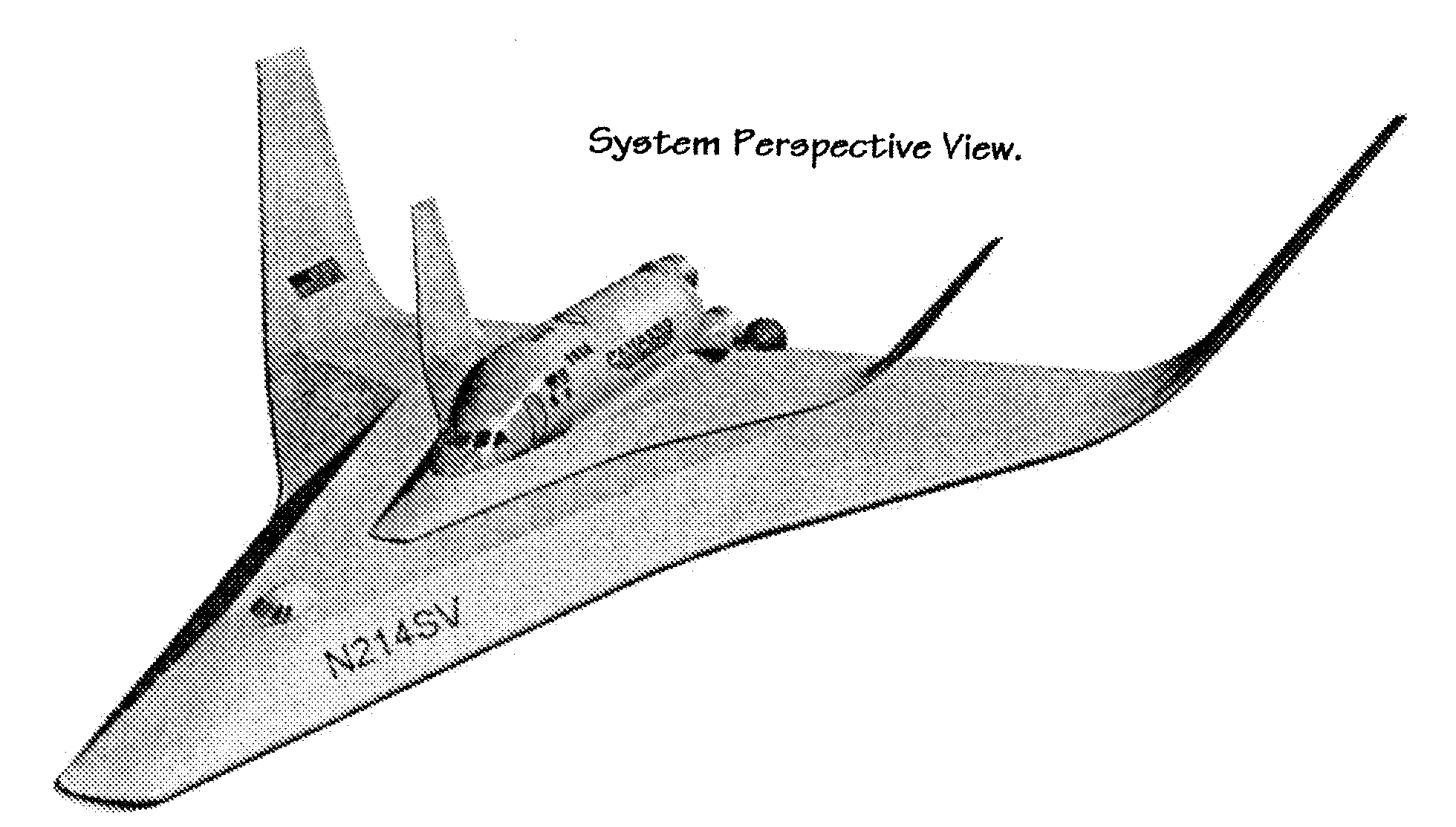
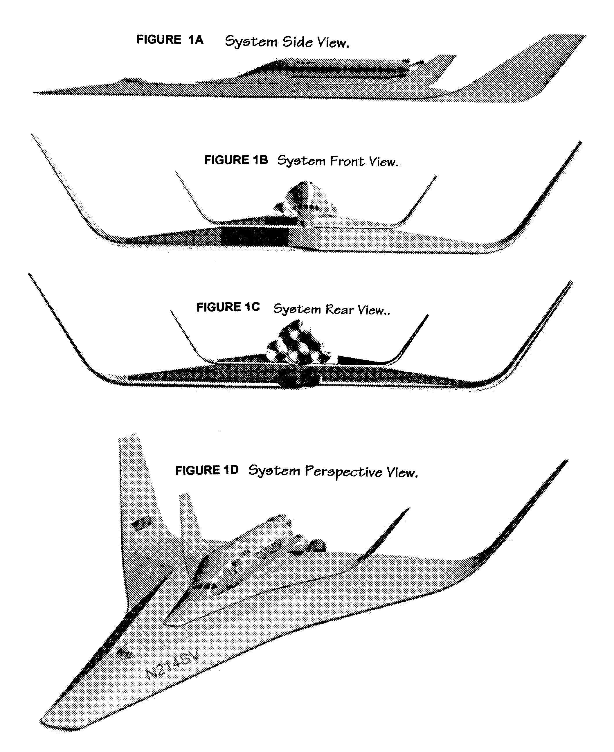
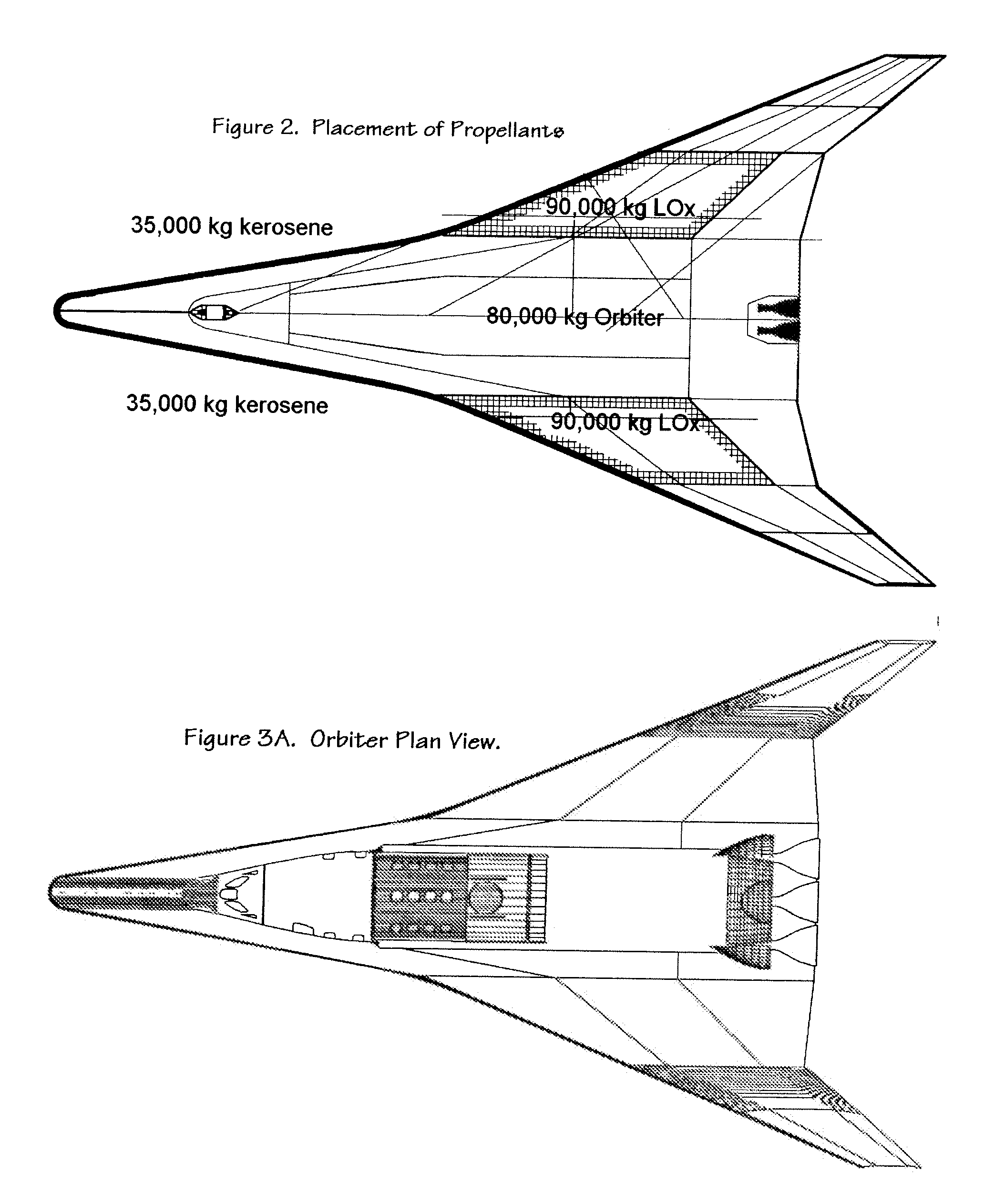
[0016]With reference to the various figures, wherein the numerals designate like components throughout all the several figures, the invention finds particular application in this preferred embodiment. This preferred embodiment is a TSTO space transport, comprising a carrier as the first stage and an orbiter as the second stage.

[0017]The carrier features a large, 1000 m2 wing that is significantly larger than might otherwise be considered for a space launch application employing horizontal takeoff and landing. This unusually large wing results in a relatively gently ride to the staging point for the orbiter, the structure of which benefits greatly from being designed for mechanical and thermal loads typical of a low planform reentry. Unlike other horizontal takeoff or vertical takeoff space transports, the orbiter stage does not experience the large structural and panel loads normally encountered in climb and acceleration to the staging point. This relief, in turn, permits a larger o...


PUM


Abstract

A two-stage space vehicle is provided for achieving low earth orbit that includes a carrier and an orbiter. The carrier has a large airfoil area relative to its dry weight, and the thrust of the rocket engine is controlled such that the carrier achieves a launch altitude and speed for the orbiter without exceeding a wingloading pressure beyond 3,500 Pa., which allows the carrier to be inexpensively constructed. Liquid propellant for the rocket engine is advantageously stored within the relatively large airfoil of the carrier, which is preferably a delta wing. The ratio of airfoil area to dry weight is about 33 m2 per ton, which allows the carrier to descend and land after launching the orbiter with low wingloading on the order of 300 Pa.

Description

FIELD OF THE INVENTION[0001]This invention is generally concerned with a high altitude aircraft, and is specifically concerned with an ultralight, large lift surface, rocket propelled aircraft for obtaining extreme altitudes suitable for staging with a second stage capable of reaching low Earth orbit.BACKGROUND OF THE INVENTION[0002]Various approaches to both expendable and reusable designs for space launch vehicles are known in the prior art. In most of these approaches, rocket propulsion supplies the primary, if not exclusive means for lift. Relatively little of the lifting forces are generated aerodynamically. This is particularly true for vertical takeoff designs, wherein wings are generally superfluous for climb and acceleration. Horizontal takeoff designs are known, wherein aerodynamic lift allows reduction in engine thrust to help compensate for wing mass. However, horizontal takeoff designs favor relatively small wings to allow efficient climb and acceleration at relatively ...

Claims


Application Information

Patent Timeline
Patent Type & Authority Applications(United States)
IPC IPC(8): B64G1/14B64G1/40B64G1/00
CPCB64G1/005B64G1/402B64G1/401
Inventor CORMIER, LEONARD N.
Owner CORMIER LEONARD N
Why Eureka
Try Eureka