Method of heating sub sea esp pumping system

a pumping system and sub-sea technology, applied in the direction of survey, insulation, borehole/well accessories, etc., can solve the problems of locking the pump impeller, the difficulty of starting up the system after a shutdown, etc., and achieve the effect of reducing the resistance to flow

Active Publication Date: 2009-07-16
BAKER HUGHES INC
View PDF21 Cites 24 Cited by
  • Summary
  • Abstract
  • Description
  • Claims
  • Application Information

AI Technical Summary

Benefits of technology

[0007]Disclosed herein is a method of handling fluid in a borehole, the method may include providing an ESP system in the borehole. The ESP system may include a pump, a pump motor, and an electrical power supply in communication with the pump motor. The method further includes inductively heating the pump motor to generate heat energy, heating fluid in the borehole with heat generated by the pump motor, and pumping the heated fluid with the pump. The heat energy generated can be transferred to fluid adjacent the motor or to the pump. Transferring the generated heat energy from the pump motor can be accomplished using working fluid sealed in a heat transfer system. The method can further involve sensing motor and / or fluid temperature. The method can further include adjusting inductively heating the motor based on sensing the motor and / or fluid temperature. Voltage provided to the pump motor can be supplied at a value lower than voltage supplied during normal operation, this can be performed while providing power to the pump motor at a frequency higher than during normal operation. The method can further include providing power to the pump motor in a waveform that varies from the waveform provided during normal pump operation.
[0008]An electrical submersible pumping system is also described herein. In an embodiment the pumping system includes a pump having a fluid inlet, a pump motor coupled to the pump, and a heat transfer system in heat energy communication with the pump motor and fluid to be pumped by the pump. Heat generated by the pump motor can be transferred for heating the fluid to be pumped and reducing its resistance to flow. The heat transfer system can include a lower liquid portion proximate the motor in heat energy communication with the pump motor, an upper / vaporization portion in heat energy communication with the fluid to be pumped, tubes extending between the lower liquid portion and the upper / vaporization portion, and a working fluid that circulates through the lower liquid portion, the tubes, and the upper / vaporization portion. The lower liquid portion may have a first and second reservoir and tubes extending between the reservoirs. The upper / vaporization portion can include a first and second reservoir and tubes extending between the reservoirs. The upper / vaporization portion may be disposed adjacent the pump so that heat energy transferred from the upper / vaporization portion to the pump can heat fluid in the pump. The upper / vaporization portion is optionally disposed so that heat energy transferred from the upper / vaporization portion flows to fluid outside of the pump. The system may include a variable speed controller in electrical communication with the pump motor, so that manipulating the variable speed controller adjusts the electrical power delivered to the pump motor for inductively generating heat energy. A temperature sensor in communication with the variable speed controller can also be included with the system.

Problems solved by technology

One unique problem associated with these large temperature excursions is difficulty in starting up the system after a shutdown.
A similar temperature related issue is associated with hydrates which accumulate in the pump when production fluids are cooled, also locking the pump impellers.

Method used


Image

  • Method of heating sub sea esp pumping system
  • Method of heating sub sea esp pumping system
  • Method of heating sub sea esp pumping system

Examples


Embodiment Construction

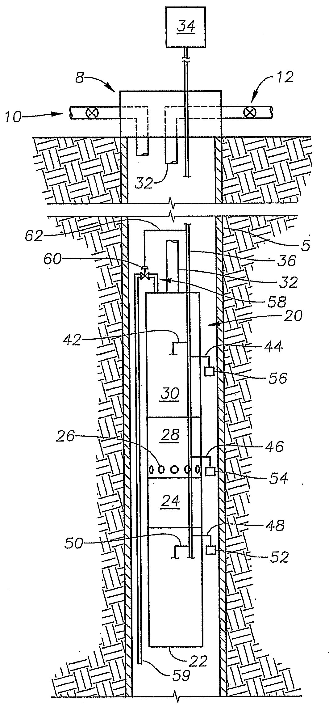
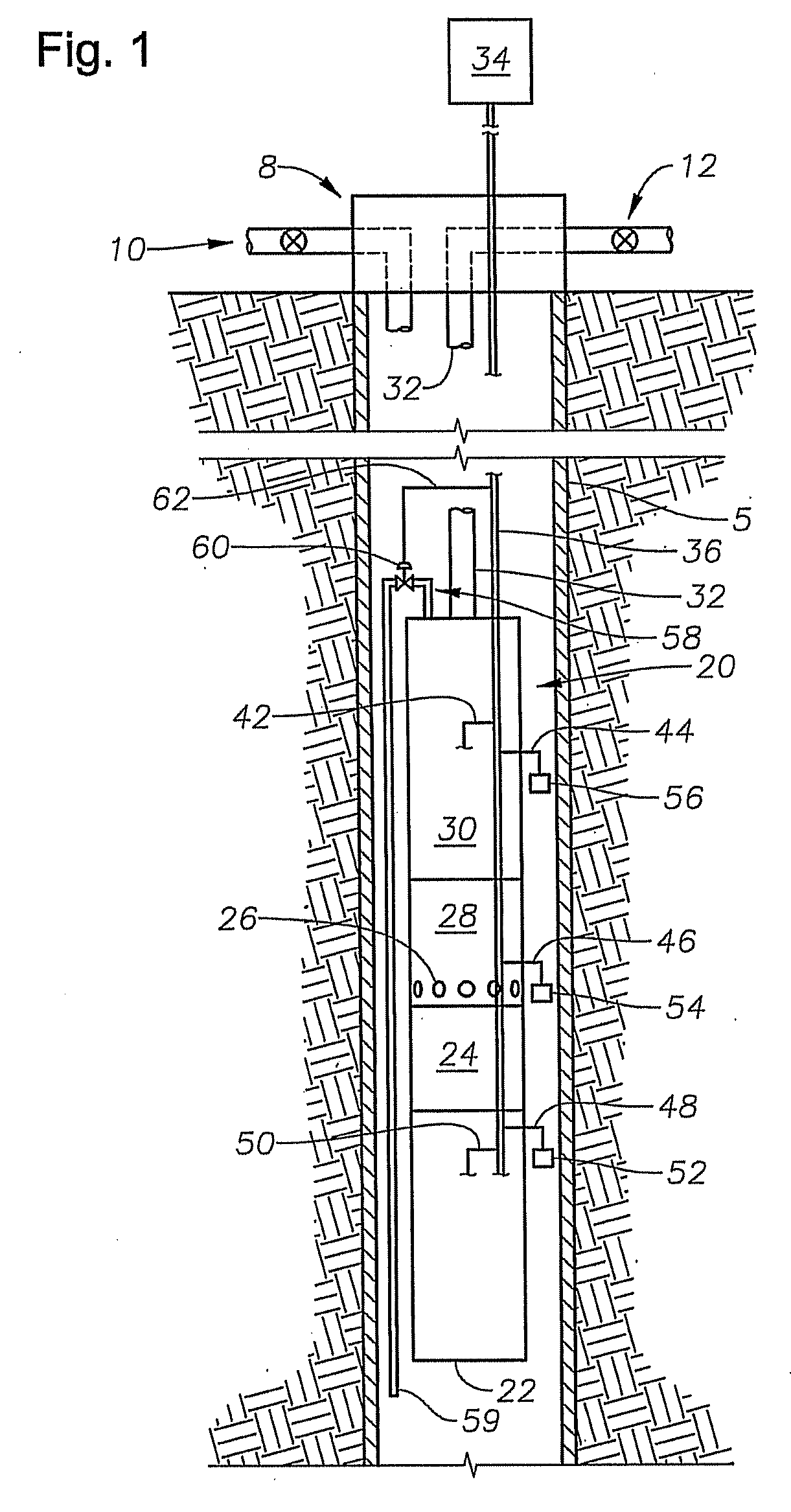
[0013]The present invention will now be described more fully hereinafter with reference to the accompanying drawings in which embodiments of the invention are shown. This invention may, however, be embodied in many different forms and should not be construed as limited to the illustrated embodiments set forth herein; rather, these embodiments are provided so that this disclosure will be thorough and complete, and will fully convey the scope of the invention to those skilled in the art. Like numbers refer to like elements throughout.

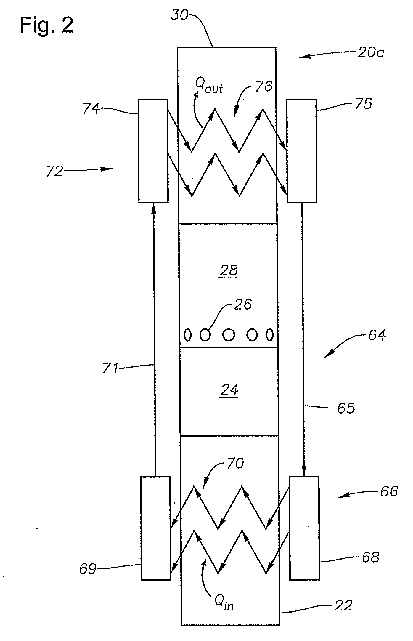
[0014]Enclosed herein is a method of handling fluid in a caisson or other borehole using an ESP system. In one embodiment, enhanced caisson or borehole fluid flow through an ESP system is described herein that includes inductively heating the pump motor of an ESP system. The heat energy generated can be transferred, either actively or passively, to heat the fluid pumped. The heat can be transferred directly to the pump or the fluid before it reaches the p...


PUM


Abstract

A system and method is provided for heating fluid to be pumped by an electrical submersible pumping system. Heat for heating the fluid may be inductively generated by adjusting the power delivered to the motor of the pumping system. In one example, the power adjustment includes supplying the voltage applied to the pump motor to a value less than voltage applied during normal operations. While lowering the voltage the electrical frequency may be varied as well as the electrical waveform.

Description

RELATED APPLICATIONS[0001]This application claims priority to and the benefit of co-pending U.S. Provisional Application Ser. No. 61 / 021,538, filed Jan. 16, 2008, the full disclosure of which is hereby incorporated by reference herein.BACKGROUND[0002]1. Field of Invention[0003]The present disclosure relates to an electrical submersible pumping system configured to heat fluid to be pumped by the system.[0004]2. Description of Prior Art[0005]Submersible pumping systems are often used in hydrocarbon producing wells for pumping fluids from within the well bore to the surface. These fluids are generally liquids and include produced liquid hydrocarbon as well as water. One type of system used in this application employs an electrical submersible pump (ESP). Submersible pumping systems, such as electrical submersible pumps (ESP) are often used in hydrocarbon producing wells for pumping fluids from within the well bore to the surface. ESP systems may also be used in subsea applications for ...

Claims


Application Information

Patent Timeline
Patent Type & Authority Applications(United States)
IPC IPC(8): E21B43/00E21B43/24E21B47/06F04D13/02
CPCE21B36/04E21B43/128F04D29/588F04D25/0606F04D13/10
Inventor NEUROTH, DAVID H.LAWSON, PETER F.EVENSON, JIM F.
Owner BAKER HUGHES INC
Why Eureka
Try Eureka