
Light modulator, projection display apparatus and image projection method

a projection display and light modulator technology, applied in the direction of instruments, static indicating devices, optical elements, etc., can solve the problems of asymmetric deformation of the positive and negative polarities of the ac voltage waveform, flickering of the projected image, and low contrast and narrow display gradation, so as to achieve the effect of lowering the cost of the projection lens

Active Publication Date: 2009-07-16
JVC KENWOOD CORP A CORP OF JAPAN
View PDF4 Cites 19 Cited by
  • Summary
  • Abstract
  • Description
  • Claims
  • Application Information

AI Technical Summary

Benefits of technology

[0024]A purpose of the present invention is to provide a light modulator, a projection display apparatus and an image projection method that can avoid projection of the shade of an optical sensor on projected images, with easer reinstallation and a lower cost for a projection lens.
[0025]Another purpose of the present invention is to provide a light modulator, a projection display apparatus and an image projection method with accurate and short-time Vcom-adjustments with a few number of optical sensors.
[0026]Still, another purpose of the present invention is to provide a light modulator, a projection display apparatus and an image projection method that can restrict flickers even if the flickers irregularly occur over a projected image and also can restrict flickers caused by the insufficient performance of liquid crystal display devices, separately from lamp flickers.

Problems solved by technology

The AC voltage waveform, however, suffers asymmetric deformation between the positive and negative polarities when applied across the common electrode and each pixel electrode.
The shifted DC voltage is then supplied to the liquid crystal display device, thus resulting in flickers occurring on projected images.
When flickers occur on projected images, they cause the images to suffer higher black levels which lead to lower contrast and narrower display gradation.
Moreover, while flickers are occurring, DC voltages being supplied to the liquid crystal display device cause ionic substances involved in liquid crystals to be pulled to either of the common or pixel electrode.
Such a phenomenon leads to burning on the liquid crystal display device, resulting in lower operational reliability of the display device.
However, the known projection display apparatus of Citation 1 has the following disadvantages due to the optical sensor provided at an outer edge of the screen or in the optical system.
When the optical sensor is provided at an outer edge of the screen, it cannot detect enough optical intensity for Vcom-adjustments because the outer edge of the screen is always at a black level during image projection.
The arrangements of several optical sensors, however, require wider space at the outer edges of the screen and the integration of detected signals causes a longer Vcom-adjustment period.
Thus, reinstallation cannot be done easily.
When the optical sensor is installed in the optical system of the known projection display apparatus, it must be located on the optical path from the liquid crystal display device in the optical system to the screen, which may result in the shade of the optical sensor being projected onto the screen.
Moreover, installation of the optical sensor in the optical system causes a higher cost for the optical system.
The single optical sensor requires three times of irradiation of R-, G- and B-rays, which results in a longer Vcom-adjustment period.
Installation of the optical sensors for the colors of R, G and B causes increase in the number of sensors and the installation space, which results in difficulty in reinstallation of the optical sensors when the projection display apparatus is moved to another place.
Moreover, flickers that occur on projected images involve a flicker so-called a lamp flicker of light discharged from the light source depending on the temperature of the electrode of the light source and the surface conditions of the electrode, in addition to an unadjusted Vcom level.
The known projection display apparatus inevitably performs excessive Vcom-adjustments to the flickers involving the lamp flicker, which may result in failure of the Vcom-adjustments, or incomplete flicker elimination.

Method used


Image

  • Light modulator, projection display apparatus and image projection method
  • Light modulator, projection display apparatus and image projection method
  • Light modulator, projection display apparatus and image projection method

Examples


Embodiment Construction

[0047]In the following disclosure and throughout the drawings, the same or analogous elements or components are given the same numerals or signs, overlapping description being omitted if not necessary.

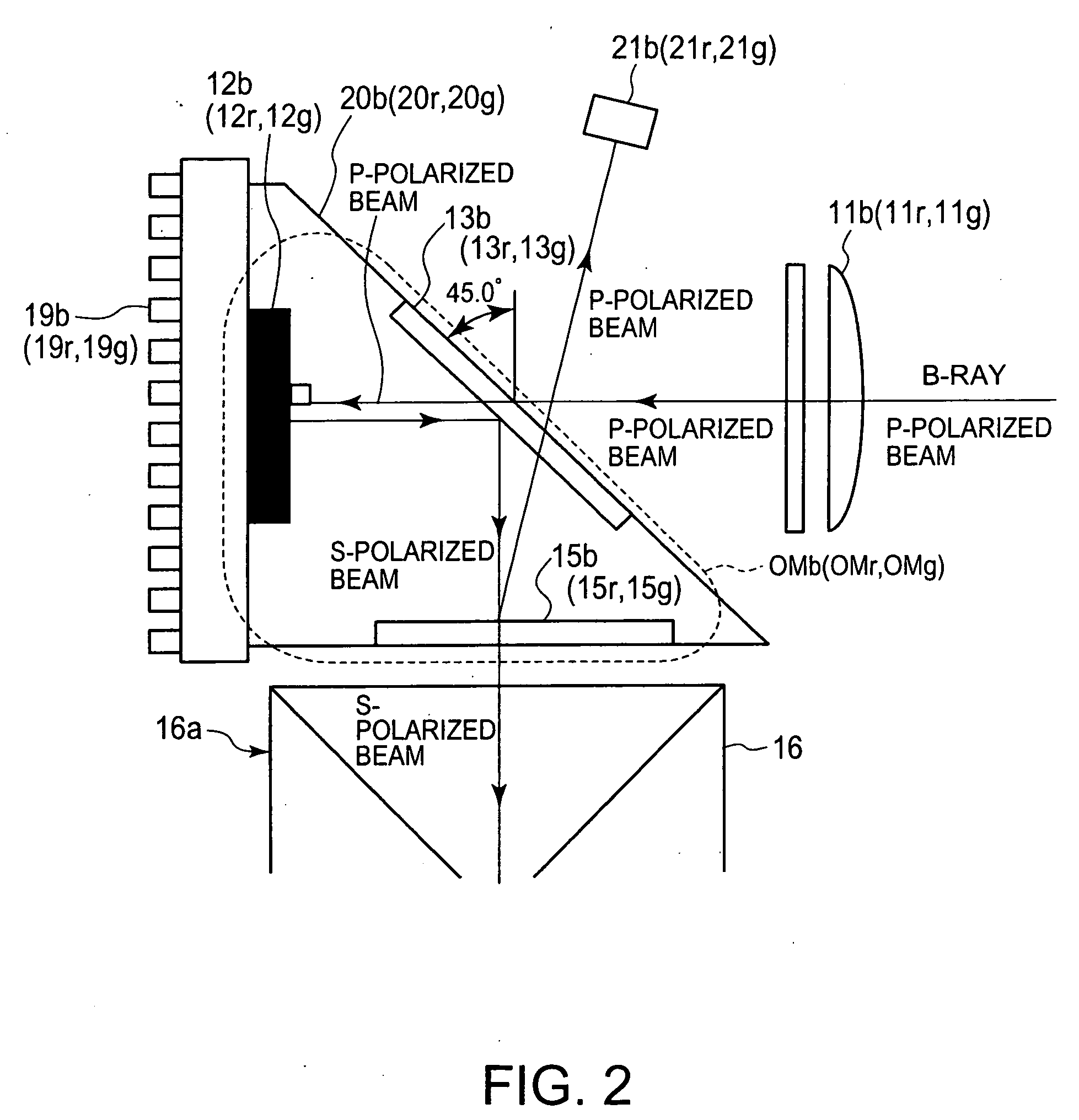
[0048]Moreover, in the following disclosure, the term “a bundle of rays” may be interpreted as “luminous flux”. Furthermore, the term “ray” is referred to as “beam” when polarization is concered.

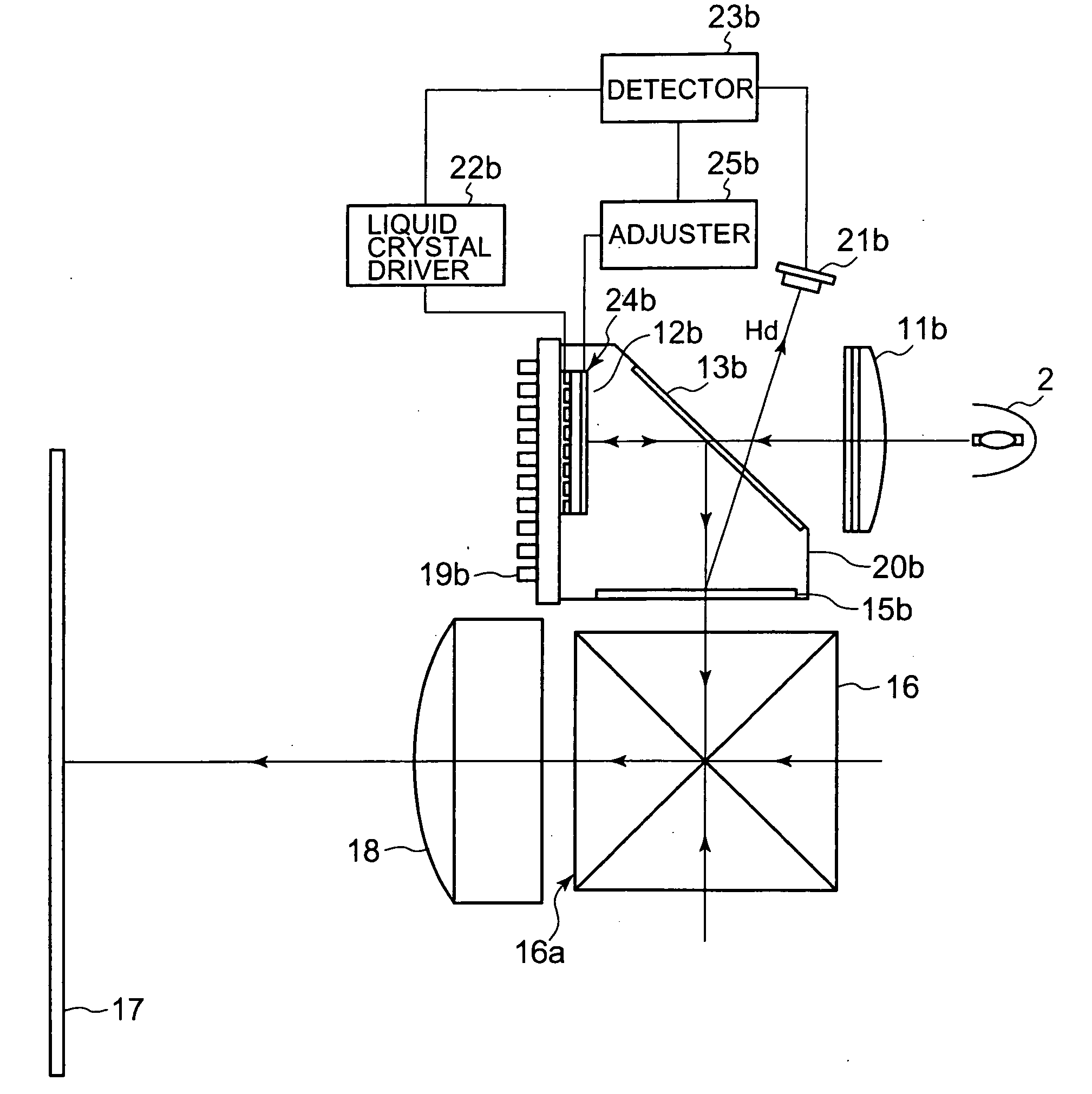
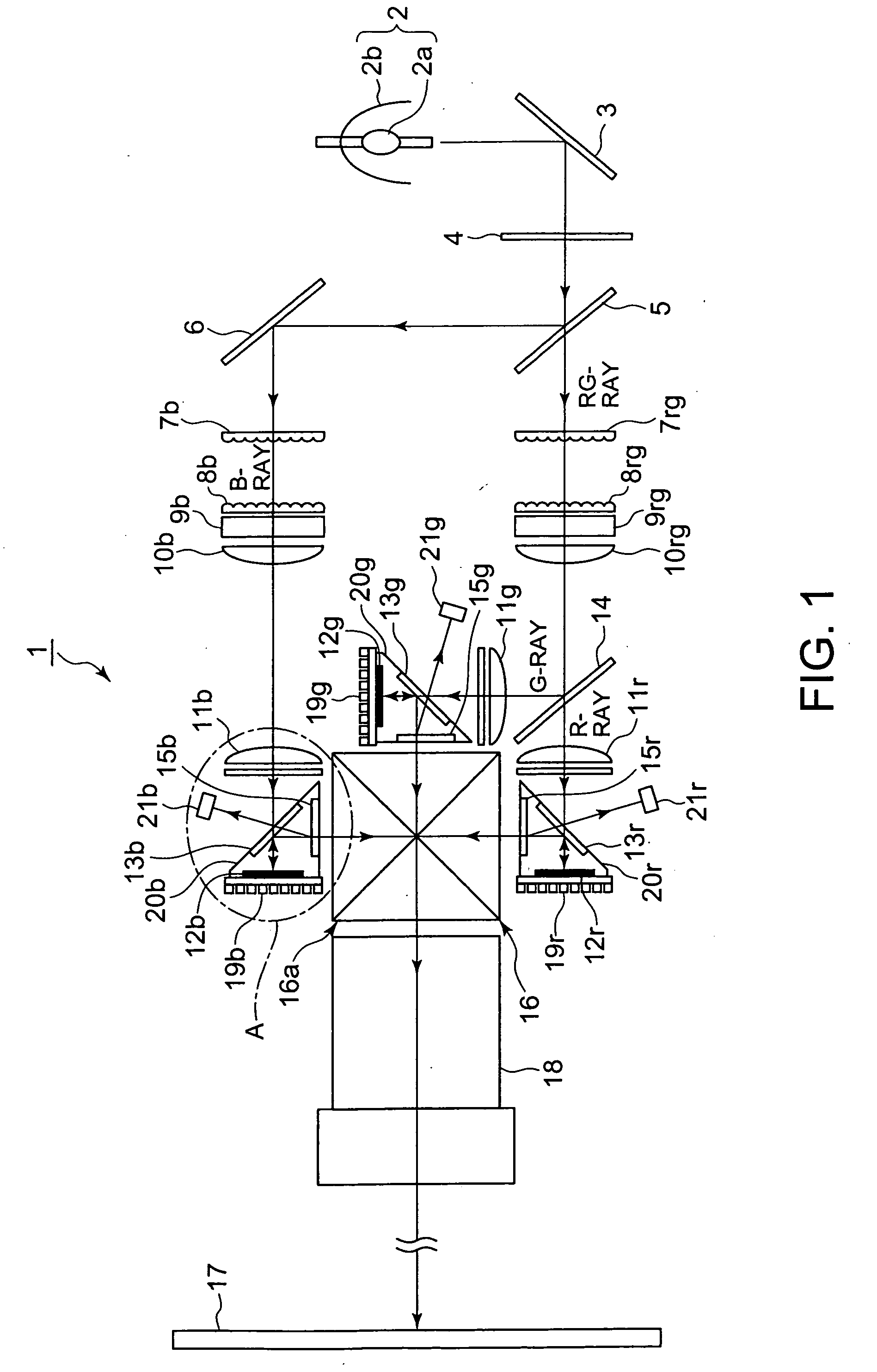
[0049]FIG. 1 shows a schematic illustration of an optical system of a projection display apparatus 1, as a preferred embodiment of the present invention.

[0050]As shown in FIG. 1, the optical system of the projection display apparatus 1 is equipped with: a light source 2 having a xenon lamp 2a and a concave mirror 2b; an infrared-ray pass filter 3 that allows an infrared ray to pass therethrough while reflects the other rays; an ultraviolet-ray reflection filter 4 that reflects an ultraviolet ray while allows the other rays to pass therethrough; and a B-dichroic mirror 5 that separates an incide...


PUM


Abstract

A first linearly polarized bundle of rays of incident rays is converted by optical modulation with an input video signal into a second linearly polarized bundle of rays orthogonal to the first rays in polarization. The first rays pass through a polarizer before optically modulated. A second linearly polarized bundle of rays originally involved in the incident rays is reflected by the polarizer in a first direction. The second rays obtained by the optical modulation are reflected by the polarizer in a second direction. The second rays reflected in the second direction pass through another polarizer. A first linearly polarized bundle of rays involved in the reflected second rays is reflected by the other polarizer. The reflected first rays is detected by an optical sensor that is positioned outside an optical path of the second rays originally involved in the incident rays and reflected in the first direction.

Description

CROSS-REFERENCE TO RELATED APPLICATIONS[0001]This application is based on and claims the benefit of priority from the prior Japanese Patent Application Nos. 2008-006856 filed on Jan. 16, 2008, and 2008-221198 filed on Aug. 29, 2008, the entire contents of which is incorporated herein by reference.BACKGROUND OF THE INVENTION[0002]The present invention relates to a light modulator, a projection display apparatus and an image projection method that achieve higher image quality for images projected onto a screen while restrict flickers that occur due to asymmetric waveforms of AC voltages applied to electrodes that face each other in a liquid crystal display device.[0003]Projection display apparatuses have a mechanism in which light is emitted from a light source to a liquid crystal display device that forms an optical image corresponding to an input video signal, which is then projected onto a screen.[0004]One factor that affects the quality of images projected onto a screen in project...

Claims


Application Information

Patent Timeline
IPC IPC(8): G09G5/02G02F1/1335
CPCG09G3/3614G09G3/3655H04N9/3194G09G2360/145H04N9/3167G09G2320/0247
Inventor UCHIYAMA, YUJIFURUYA, MASATOKOBAYASHI, TATSURUNISHIMA, RYOTOHDA, MOTOSHIFUKUZAKI, YOSHIOMAKABE, TAKESHIISHIZAKA, YASUOHAMAGUCHI, AKIHIRO
Owner JVC KENWOOD CORP A CORP OF JAPAN
Learn More