Physiological signal measuring sensor and manufacturing method for the same

a technology of physiological signal and manufacturing method, which is applied in the direction of medical science, diagnostics using light, diagnostics, etc., can solve the problems of reducing limiting the reliability of such a product, and generating measurement errors, so as to reduce size, maintain measurement accuracy, and minimize measurement errors

Inactive Publication Date: 2009-07-16
SAMSUNG ELECTRONICS CO LTD
View PDF7 Cites 80 Cited by
  • Summary
  • Abstract
  • Description
  • Claims
  • Application Information

AI Technical Summary

Benefits of technology

[0009]The present invention also provides a physiological signal measuring sensor that minimizes the measurement error caused by a soldering tolerance during a manufacturing process, and a manufacturing method for the same.
[0010]The present invention also provides a physiological signal measuring sensor that maintains measurement accuracy while measuring a plurality of physiological signals and having a reduced size, and a manufacturing method for the same.

Problems solved by technology

However, since the conventional physiological signal measuring sensor is manufactured by mounting a light emitting device and a light receiving device that are separately manufactured to a printed circuit board, the manufacturing process is complex and there is a limit in maintaining the reliability of such a product.
In other words, the light emitting device and the light receiving device soldered to the printed circuit board have undesired height deviations and angle deviations, and as such a measurement error is generated in the conventional physiological signal measuring sensor.
In particular, since a skin color measuring sensor is installed close to a light emitting device and a light receiving device, a minute angle change of the light emitting device causes a light path change in a skin layer, generating a severe measurement error.
This is bothersome to a user.

Method used


Image

  • Physiological signal measuring sensor and manufacturing method for the same
  • Physiological signal measuring sensor and manufacturing method for the same
  • Physiological signal measuring sensor and manufacturing method for the same

Examples


first embodiment

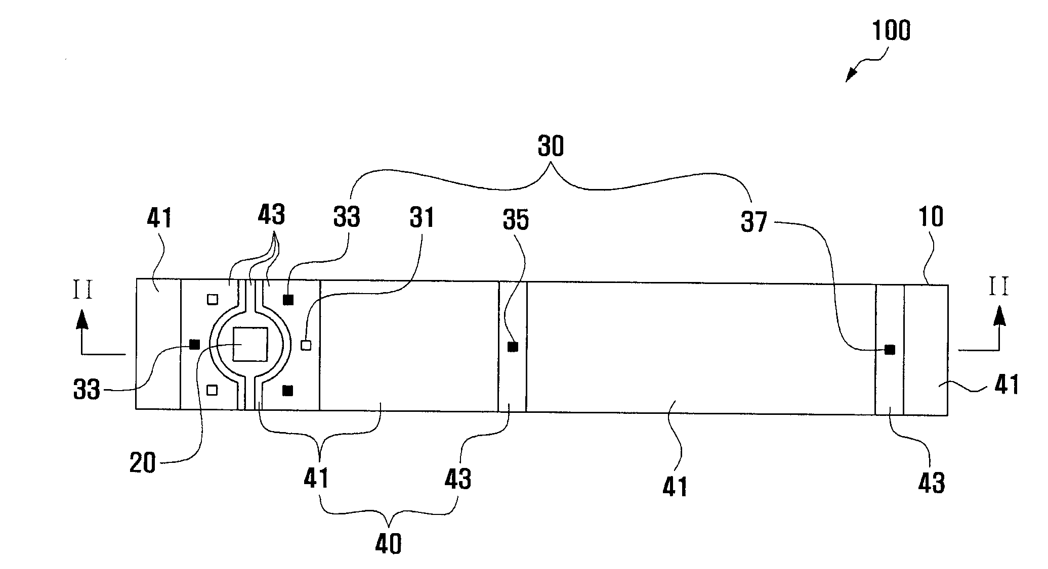
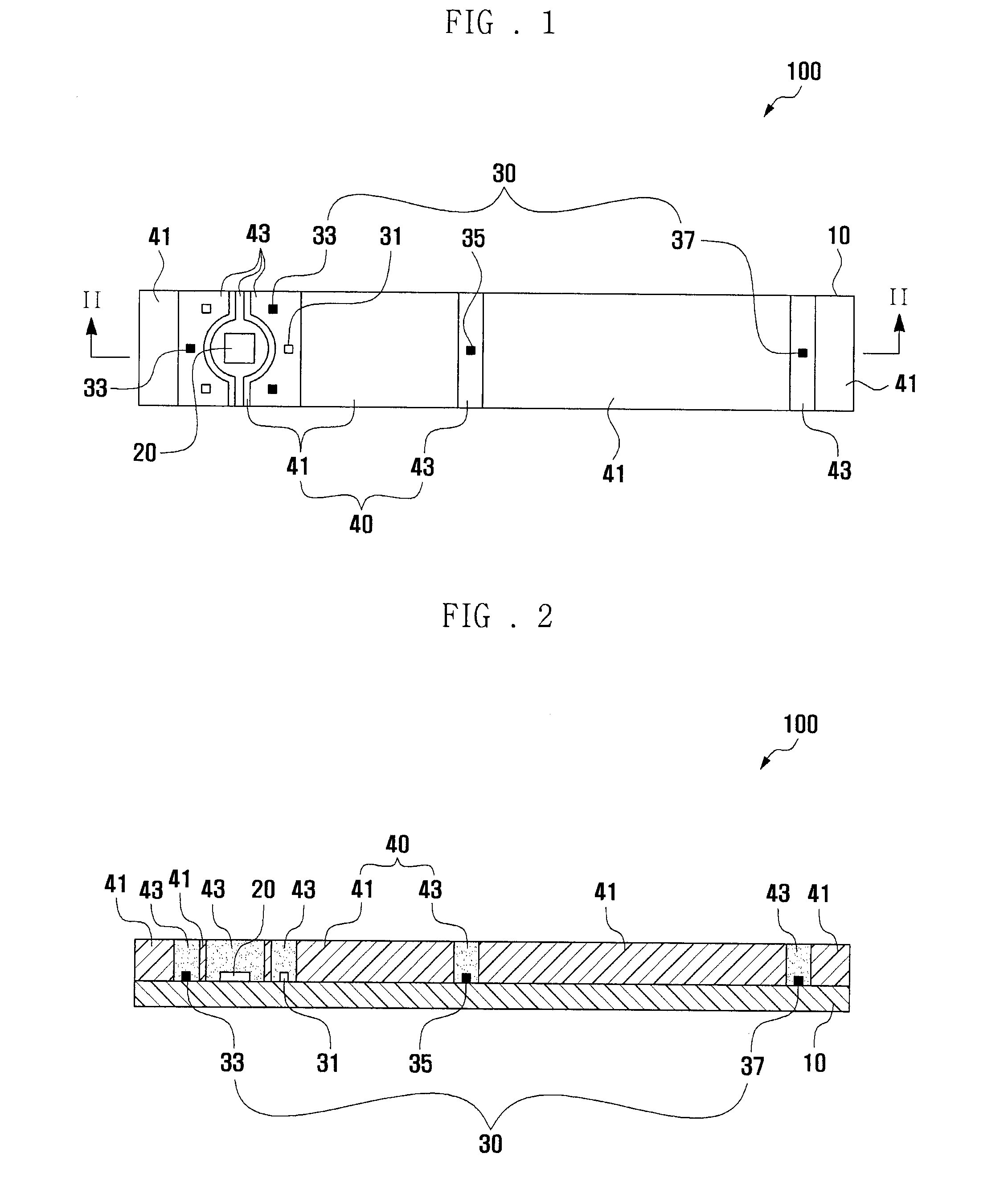
[0034]Since the light receiving chip 20 and the light emitting chips 30 are directly mounted to the printed circuit board 10 and are sealed by the resin sealing portions 40, the heights and angles of the resin sealing portions 40 contacted with a skin are all substantially identical. Hence, the physiological signal measuring sensor 100 according to the present invention minimizes the measurement deviation of the product.

[0035]The physiological signal measuring sensor 100 according to the first embodiment of the present invention is now described in detail.

[0036]The printed circuit board 10 is a rectangular wire board, and its transverse length is longer than its longitudinal length.

[0037]The light receiving chip 20 is mounted to one side of the upper surface of the printed circuit board 10, and receives the light reflected by the portion of the human body and measures a physiological signal by detecting the intensity of the received light. A photodiode is generally used as the light...

sixth embodiment

[0062]Meanwhile, since outputs of light emitting chips are varied according to the temperature of the environment where a physiological signal measuring sensor is located, as illustrated in FIG. 9, a physiological signal measuring sensor 600 according to the present invention may further include a temperature compensation device 550 that measures the temperature of the environment where it is used.

[0063]The temperature compensation device 550 is mounted to the upper surface of a printed circuit board 510 and may be sealed by a first resin sealing portion 541. In particular, the temperature compensation device 550 is preferably disposed close to the first and second light emitting chips 531 and 533 that measure a skin color whose value is severely changed according to the temperature of the physiological signal measuring sensor 600. In other words, the temperature compensation device 550 is mounted to the printed circuit board 510 between the first and second light emitting chips 531...

seventh embodiment

[0074]Referring to FIGS. 14 and 15, in the physiological signal measuring sensor 700 according to the present invention, the first resin sealing portions 641 are higher than the second resin sealing portions 643. The first and second resin sealing portions 641 and 643 have different heights to prevent the second liquefied sealing resin from penetrating to the upper surface of the first resin sealing portions when the second resin sealing portions 643 are formed after the formation of the first resin sealing portions 641. Since the refraction index of a transparent epoxy resin is generally higher than that of the air, some light emitted inside the second resin sealing portions 643 is generally reflected, in total, at the border surfaces of the second resin sealing portions 643 and the air. Hence, when the liquefied second sealing resin intrudes to the upper surfaces of the first resin sealing portions 641, the light emitted from the light emitting chips 630 is wave-guided by the tran...


PUM

PropertyMeasurementUnit
distanceaaaaaaaaaa
distanceaaaaaaaaaa
thicknessaaaaaaaaaa

Abstract

A physiological signal measuring sensor that minimizes the measurement error due to a soldering tolerance during the manufacturing process, and a manufacturing method for the same is disclosed. The physiological signal measuring sensor includes a printed circuit board, a light receiving chip mounted to the upper surface of the printed circuit board, light emitting chips mounted to the upper surface of the printed circuit board adjacent to the light receiving chip and resin sealing portions sealing the light receiving chip and the light emitting chips mounted to the upper surface of the printed circuit board wherein a first resin is selected to have opaque optical characteristics and a second resin is selected to have transparent characteristics.

Description

CLAIM OF PRIORITY [0001]This application claims the benefit of the earlier filing date, pursuant to 35 USC 119, to that patent application entitled “PHYSIOLOGICAL SIGNAL MEASURING SENSOR AND MANUFACTURING METHOD FOR THE SAME” filed in the Korean Intellectual Property Office on Jan. 10, 2008 and assigned Serial No. 2008-0002932, the contents of which is incorporated herein by reference.BACKGROUND OF THE INVENTION [0002]The present invention relates to a physiological signal measuring sensor and, more particularly, to a physiological signal measuring sensor that can measure the subcutaneous fat thickness, skin color, and pulse wave of a human body together using light, and a manufacturing method for the same.[0003]Technologies for measuring physiological signals such as pulse waves, skin colors, and subcutaneous fat thicknesses using light are being developed. For example, in order to measure a pulse wave, a near infrared ray is used to measure a change in the amount of light absorbed...

Claims


Application Information

Patent Timeline
Patent Type & Authority Applications(United States)
IPC IPC(8): A61B5/00H01S4/00
CPCA61B5/0059Y10T29/49002A61B5/441A61B5/1032A61B5/00
Inventor CHO, JAE GEOLOH, JUNG TAEK
Owner SAMSUNG ELECTRONICS CO LTD
Why Eureka
Try Eureka