Ultrasound System With Integrated Control Switches

a technology of control switch and ultrasonic system, applied in the field of ultrasonic systems, can solve the problems of limiting factors such as the size and weight of the required wiring, the complexity of the ultrasonic system, and the present technical difficulties

Inactive Publication Date: 2009-07-16
GENERAL ELECTRIC CO
View PDF23 Cites 64 Cited by
  • Summary
  • Abstract
  • Description
  • Claims
  • Application Information

AI Technical Summary

Benefits of technology

[0016]According to one embodiment, the ultrasound imaging system includes a plurality of additional switchable connections to selectively transmit the pulser timing signals between circuit support cells so that a timing signal transmitted to a first support cell can effect operation of the pulser circuitry in the first support cell and the pulser circuitry in at least another one of the support cells.

Problems solved by technology

Ultrasound systems are of growing complexity, particularly in the field of medical diagnostics because of the desire to improve system performance, e.g., image resolution, while maintaining or reducing the size and weight of the probe unit.
Connecting several thousand transducer subelements to receive these driving signals from the correct channels can present technical difficulties due to the number of wire leads that must extend between the transducer array and the timing and control circuitry.
This challenge results both from the increased number of transducer elements needed to provide the desired resolution and from the requirements for constructing multi-dimensional images.
Even with the integration of the pulser circuits, which form the transducer cell driving signals, into the ASIC cells in the probe unit, the size and weight of the required wiring is a limiting factor.

Method used


Image

  • Ultrasound System With Integrated Control Switches
  • Ultrasound System With Integrated Control Switches
  • Ultrasound System With Integrated Control Switches

Examples


Embodiment Construction

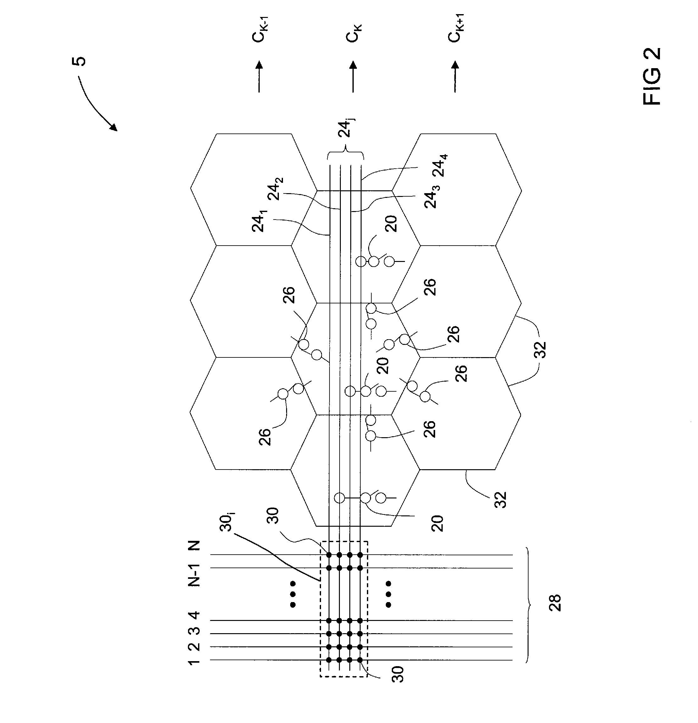
[0034]For purposes of illustration, various embodiments of the invention will be described in the context of an array 5 comprising capacitive micromachined ultrasonic transducers (cMUTs). However, it should be understood that the present invention is not limited in application to cMUT arrays, but rather may also be practiced in arrays that employ pMUTs or PZT elements or other transducers found suitable for ultrasound applications.

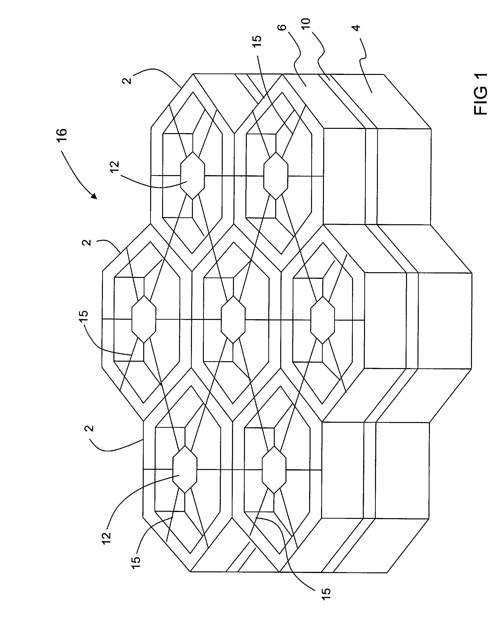
[0035]Referring to FIG. 1, a group of cMUT transducer cells 2 is schematically shown. A large array of such cMUT transducer cells 2 is typically fabricated on a substrate 4, such as a heavily doped silicon semiconductive wafer. For each cMUT transducer cell 2, a thin membrane or diaphragm (not shown), which may be made of silicon nitride, is suspended above the substrate, being supported along its periphery by an insulative support 6, typically formed of silicon oxide or silicon nitride. The resulting cavity formed between the membrane and the substrate 4 ...


PUM


Abstract

An ultrasound imaging system with a digital scanning architecture for configuring connections that transmit pulser timing signals among transducer subelements. The system provides multiple operating states that each generate a different wave pattern. An integrated circuit structure includes a plurality of circuit support cells, each including pulser circuitry for operation of at least one of the subelements. The circuit structure also includes first connections each selectable through one of multiple first access switches, these providing a timing signal to the pulser circuitry in one of the circuit support cells. Some of the support circuit cells further include one or more timing channel select switches providing selectable connections to transmit different pulser timing signals among the first access switches.

Description

STATEMENT REGARDING FEDERALLY SPONSORED RESEARCH AND DEVELOPMENT[0001]The United States Government may have certain rights in this invention pursuant to U.S. Government Contract Number 1R01 EB002485 awarded by the National Institutes of Health.BACKGROUND OF THE INVENTION[0002]This application is related to 206174-2 filed January ______ 2008. The invention generally relates to ultrasound systems of the type which incorporate application specific integrated circuits (ASICs) for use in conjunction with a two dimensional array of transducer elements. In particular, the invention includes embodiments wherein both low-voltage and high-voltage circuits are integrated within individual circuit cells of an ASIC and the ASIC is located adjacent the array of transducer elements. In such applications the probe handle is typically connected via cabling to a portable unit or a console which provides image processing and control circuitry.[0003]Image resolution is partly a function of the number o...

Claims


Application Information

Patent Timeline
Patent Type & Authority Applications(United States)
IPC IPC(8): A61B8/00
CPCG10K11/345G01S15/8925A61B8/4483
Inventor WODNICKI, ROBERT GIDEON
Owner GENERAL ELECTRIC CO
Why Eureka
Try Eureka