
Device and assembly for positioning and stabilizing an eye

a technology for positioning and stabilizing eyes, applied in the field of eye positioning and stabilizing devices, can solve the problems of eye position not maintained and verified, alignment errors, and improper alignment of patients' eyes

Active Publication Date: 2009-07-16
CARL ZEISS MEDITEC INC
View PDF102 Cites 46 Cited by
  • Summary
  • Abstract
  • Description
  • Claims
  • Application Information

AI Technical Summary

Benefits of technology

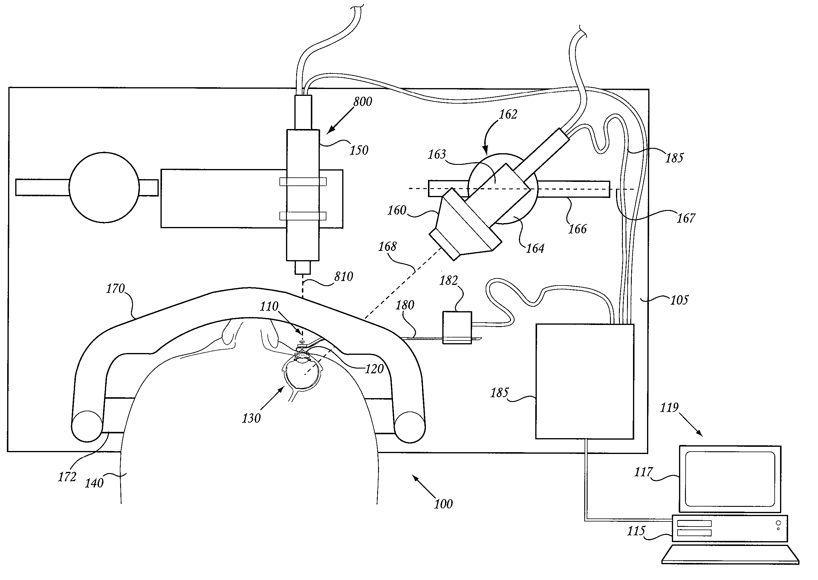
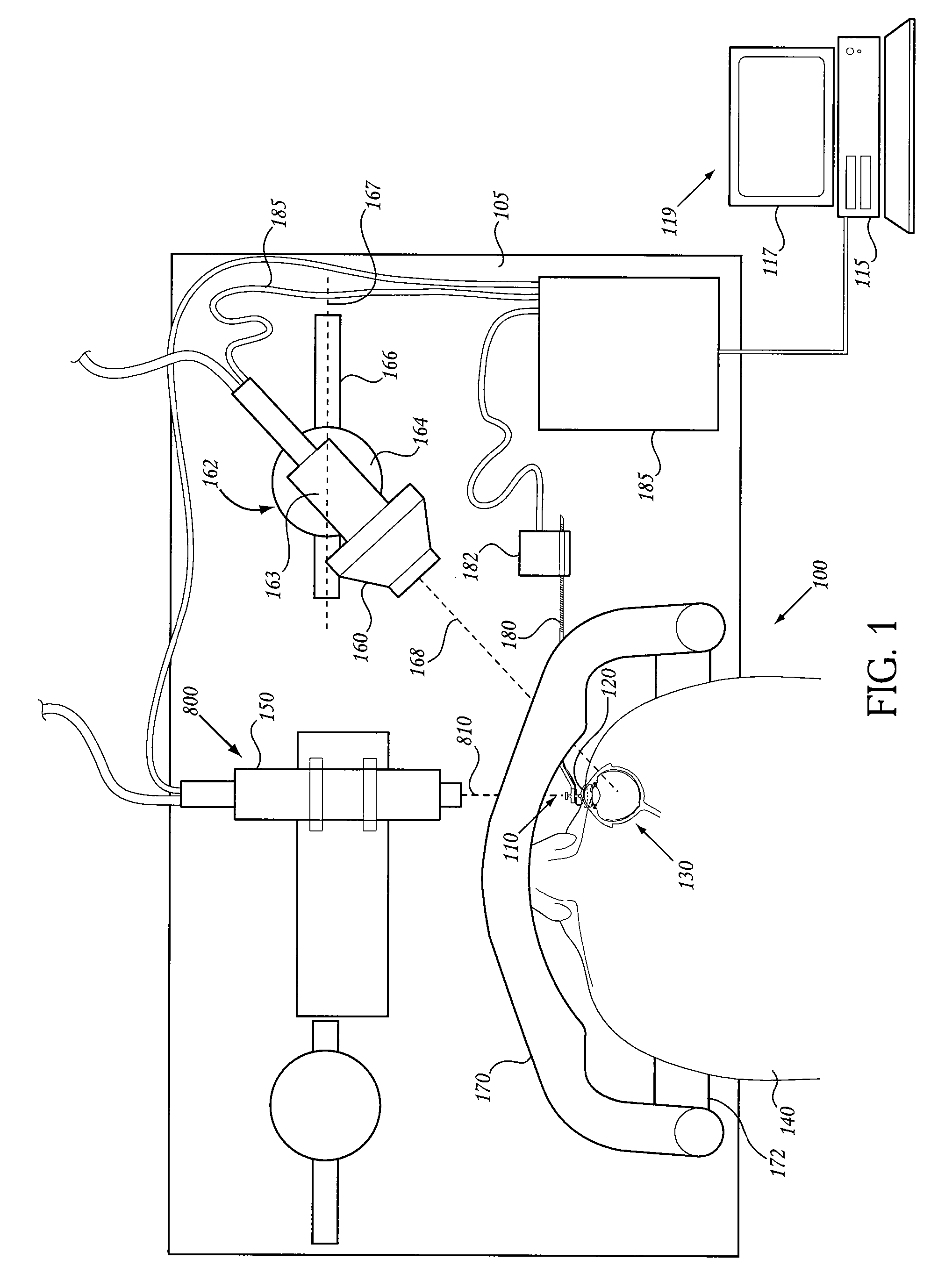
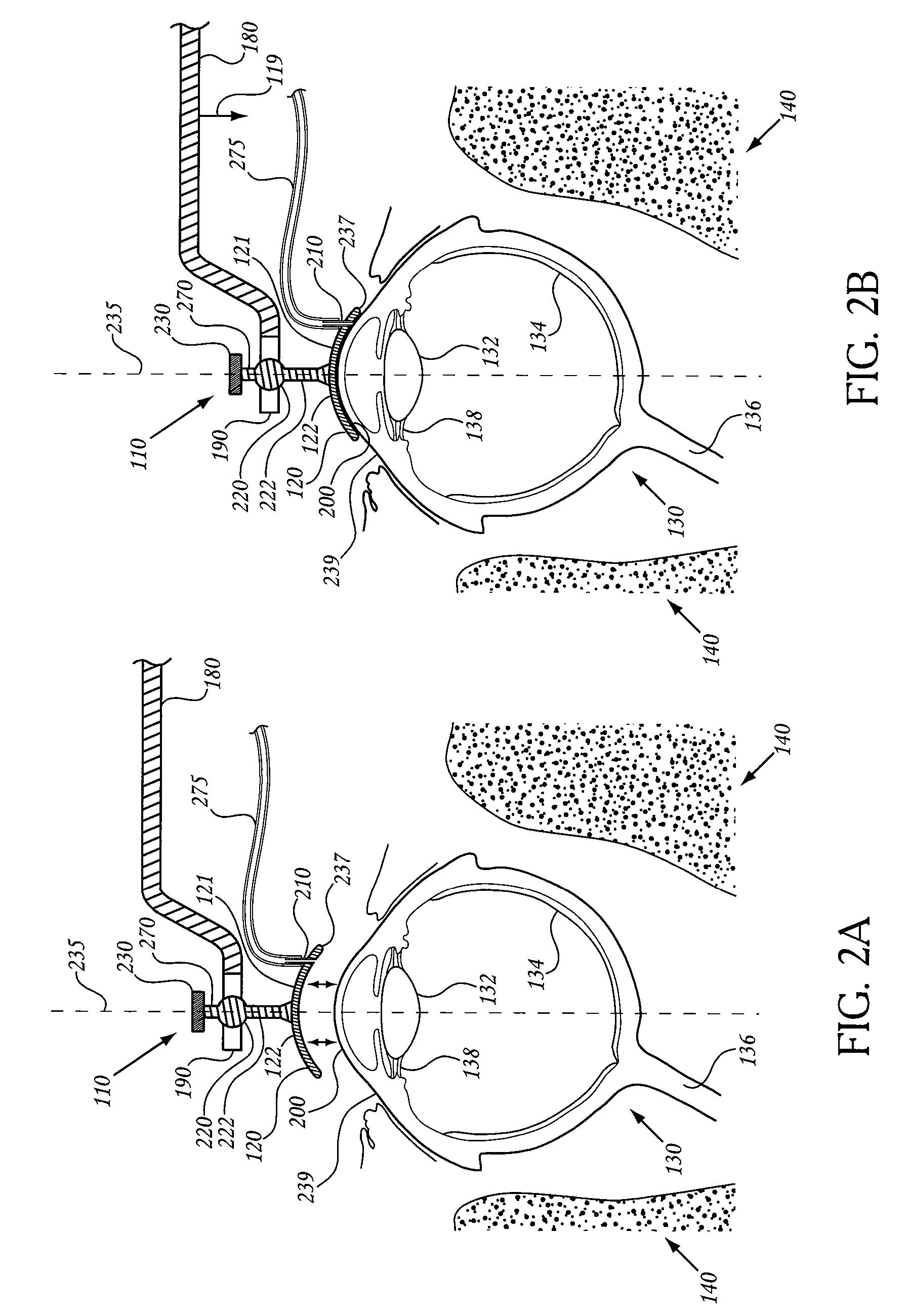
The invention is an eye-contact device for stabilizing a patient's eye in a selected position in an external coordinate system. The device includes an eye-contact member with a negative pressure vacuum reservoir for stabilizing the eye, a positioning arm for positioning the eye-contact member at a selected position, and a releasable coupling mechanism for releasably coupling the device to the arm. The device can be used in an eye-contact assembly for stabilizing the eye in a specific position in an external coordinate system. The invention also includes a reflecting surface for determining the orientation of the device in the external coordinate system and a force gauge for measuring the force applied to the eye by the biasing mechanism. The device can be used in an eye-contact assembly for stabilizing the eye in a specific position in an external coordinate system.

Problems solved by technology

A major limitation of previous radiotherapy treatment systems is that eye position was not maintained and verified, with system shut-off occurring in the case where the eye travels out of position.
This includes the improper alignment of the patient's eye relative to the treatment system.
Alignment errors may result from either a misconfiguration of the system, or from the patient's interaction with the system.
Several current laser surgery systems do not utilize direct contact between the eye and the laser system.
However, when the eye is allowed to move independently of the system, maintaining an optical alignment of the eye with a laser or treatment system is problematic.

Method used


Image

  • Device and assembly for positioning and stabilizing an eye
  • Device and assembly for positioning and stabilizing an eye
  • Device and assembly for positioning and stabilizing an eye

Examples


Embodiment Construction

[0050]Reference will now be made in detail to disclosed embodiments of the invention, examples of which are illustrated in the accompanying figures.

I. Definitions

[0051]Unless otherwise indicated, all technical and scientific terms used herein have the same meaning as they would to one skilled in the art of the present invention. It is to be understood that this invention is not limited to the particular methodology and protocols described, as these may vary.

[0052]As used herein, “accommodation” refers to the ability to change focus from distant objects to near objects, which ability may tend to diminish with age.

[0053]The term choroid” refers to the highly vascular layer of the eye beneath the sclera.

[0054]As used herein, “ciliary muscle” refers to a muscular ring of tissue located beneath the sclera and attached to the lens via zonules.

[0055]As used herein, “conjunctiva” refers to the thin, transparent tissue covering the outside of the sclera. In some embodiments of the invention,...


PUM


Abstract

An eye contact device and assembly for stabilizing a human eye at a selected position in an external coordinate system is disclosed. The device includes an eye-contact member having an inner contact surface for contacting a front surface of an eye, and a vacuum port formed within the eye-contact member by which a negative pressure can be applied between the eye and the contact surface, to stabilize the position of the eye with respect to the device. The device, which is adapted to be biased against the patient's eye, to secure the device to the eye, may be pivotally coupled to a positioning arm, and may carry one or more beam-directing elements by which the position of the device in an external coordinate system can be determined.

Description

FIELD OF THE INVENTION[0001]The present invention pertains to a device and assembly for positioning and stabilizing an eye, e.g., for performing an ocular treatment method.BACKGROUND[0002]A number of treatment and surgery procedures require a patient's eye to be stabilized or positioned prior to and / or during treatment. For example, refractive laser surgery involves ablating corneal tissue of the eye with an ultra-fast, ultra-short pulse duration laser beam. The ablation of selected corneal tissue can correct refractive errors in a patient's eye by permanently altering the structure of the cornea. To achieve ablation, refractive laser surgery requires a laser beam to be precisely focused to a very small focal spot within the cornea. As such, the patient's eye must be stabilized, and either the laser system must be properly and precisely aligned with the patient's eye, or the patient's eye must be properly and precisely aligned with the laser system.[0003]In order to achieve proper a...

Claims


Application Information

Patent Timeline
Patent Type & Authority Applications(United States)
IPC IPC(8): A61F9/007
CPCA61F9/00821A61N5/1017A61F2009/00863A61F9/008A61F2009/00895A61F9/00819A61F2009/00872A61F2009/00865A61F9/00804A61B17/0231A61F9/009
Inventor GERTNER, MICHAELARNOLDUSSEN, MARKHERRON, MATT
Owner CARL ZEISS MEDITEC INC
Learn More