Parabolic solar trough systems with rotary tracking means

a technology of solar collectors and rotary tracking means, which is applied in the direction of solar heat collectors for particular environments, solar radiation concentration, moving/orienting solar heat collectors, etc. it can solve the problems of only decreasing the rate of breaking of the structure, increasing the possibility of breaking of both reflectors and tubes during operation, and reducing the bending and torsion effect of the motor, so as to reduce the load on the motor and reduce the bending and torsion

Inactive Publication Date: 2009-07-23
HSE HITIT SOLAR ENERJI ANONIM SIRKETI
View PDF19 Cites 26 Cited by
  • Summary
  • Abstract
  • Description
  • Claims
  • Application Information

AI Technical Summary

Benefits of technology

[0010]An aim of the invention is to provide solar collectors with parabolic reflector, which rotate around a fixed thermal receiver tube, to direct more sensitively towards the sun by using synchronously running motors with each other, and to have the motors run, even if some of them fail, without any need to stop entire collector system.
[0011]Other aim of the invention is to support the convex parts of the parabolic reflectors with lightweight and resistant filling materials and decrease the bending and the torsion effects generated by the wind. It is also aimed, owing to a more lightweight collector system, to decrease the load imposed on the motor and thus save the electric energy which is necessary to rotate the system.
[0012]Another aim of the invention is to use guy wires between the circle and its center in order to reduce the weight of the support circles used at certain intervals throughout the parabolic reflectors, and also to reduce the weight of the present circle more and use them at more frequent intervals, thus increasing the resistance against the wind loads.

Problems solved by technology

However, since thermal receiver tubes used in these systems are many meters long, said thermal receiver tubes follow the sun together with the reflectors, outer parts thereof are made of glass, such factors increase their possibility of breaking during operation.
In addition, dynamic and static forces which are generated by the wind can cause both reflectors and tubes to break.
However, this structure decreases only the rate of breaking and is not a complete solution for breaking.
The vibrations generated as a result of the movement which is made by the system for directing towards the sun can also cause the glass tubes to break.
The most fundamental problem of this system is that the thermal receiver tubes which are made of a fragile material are movable.
The thermal receiver tubes which are subjected to the torque loads have a higher possibility of breaking.
On the other hand, it is understood that the flexible hose connection is not a safe system since the temperature of the fluid which is transferred within the thermal receiver tube is 300-500° C. In addition, it has been obtained from the field observations that the truss structure, which supports the parabolic mirrors, is also weak against the torque and the moment loads acting due to the drive unit of the system and the wind.
Because of these loads, the parabolic reflectors are frequently broken, thus causing the operating costs to increase.
Although the truss system which is developed with EUROTROUGH is safer than the system of LUZ, it could not strictly eliminate the breaking problem of the parabolic reflectors and the thermal receiver tubes.
In addition, it has been also revealed from the field observations that the hot fluid frequently leaks out from these connections of the thermal receiver tubes comprising rotary joint connection points.
Another problem observed with LUZ and EUROTROUGH is that the hydraulic pistons of both systems cannot move with the required sensitivity to follow the sun.
It is highly difficult and generates an adjustment problem to make a sensitive speed control with the hydraulic piston units and provide simultaneous operations of multiple piston units which are used for multiple parabolic reflectors.
Additionally, in both systems, while following the sun, continuous displacement of the center of gravity causes more energy consumption to run these systems.
However, in this system, providing the movement of all parabolic reflectors with a single motor unit causes the entire system to stop in case of a failure of this motor unit.
In addition, efforts are put forth to rotate all parabolic reflectors synchronously with one motor; but in this case, it is not possible to rotate them with the same sensitivity with respect to one another.
On the other hand, it is very difficult and expensive process to produce the parabolic reflectors integrally, and a breaking which can occur in the reflectors causes all reflectors to be changed.
Placement of the circular support parts which are used in this system onto the wheels which stand close to each other reciprocally also produces a balance problem in the system and causes the reflectors to be more affected by the wind loads.
Standing wheels too close to each other and locating them on the lowest portion of the reflectors cause the reflectors to be more affected by the wind loads.
Manufacturing cost of the single-piece parabolic reflectors in the systems of the prior art accounts for 20% of the entire system cost, which is an important part thereof.
Difficulties are encountered during the direct steam generation in the thermal receiver tubes with flexible hose connection or rotary joint connection which are used in the prior art, and the generated steam leaks out to external environment from said connection points.

Method used


Image

  • Parabolic solar trough systems with rotary tracking means
  • Parabolic solar trough systems with rotary tracking means
  • Parabolic solar trough systems with rotary tracking means

Examples


Embodiment Construction

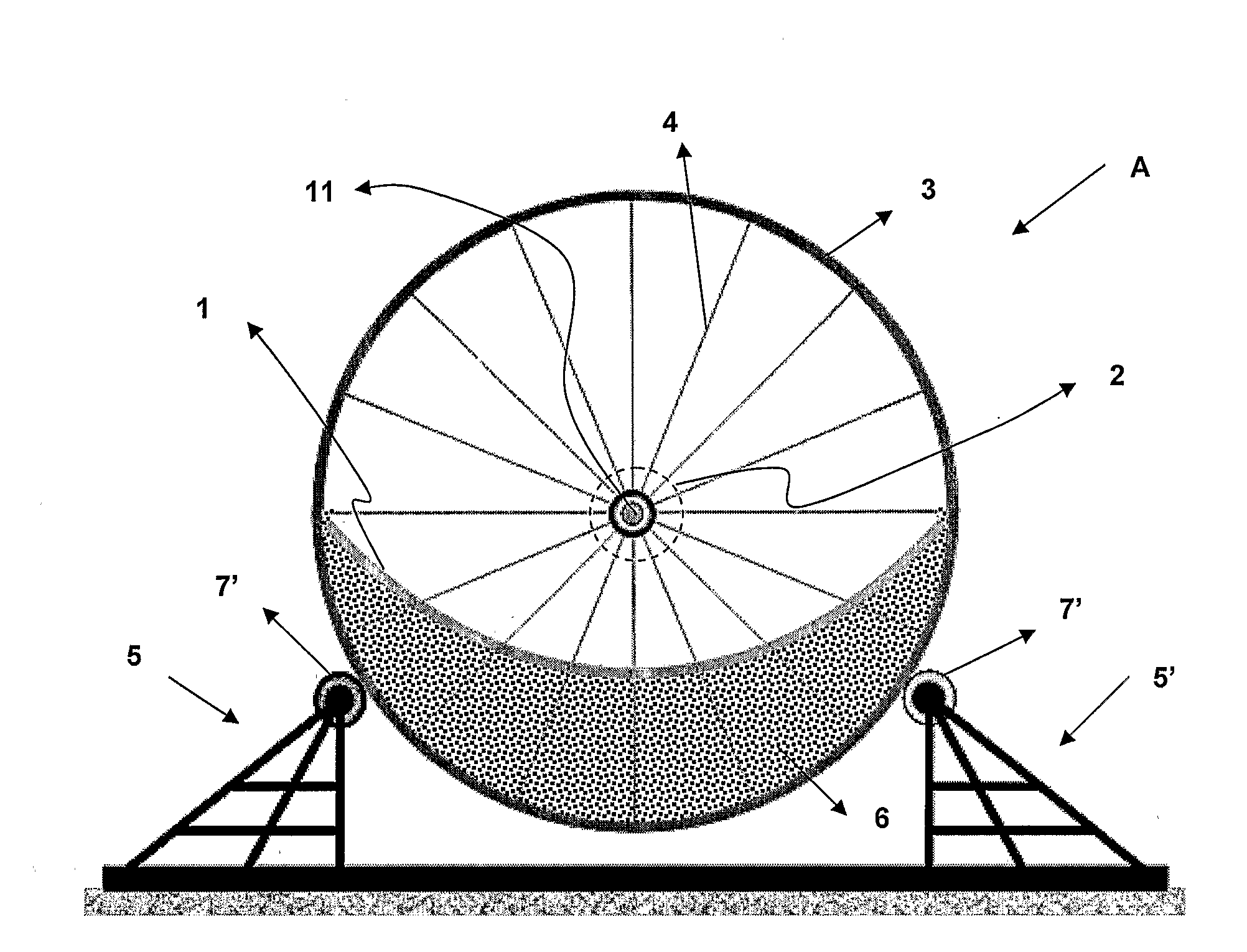
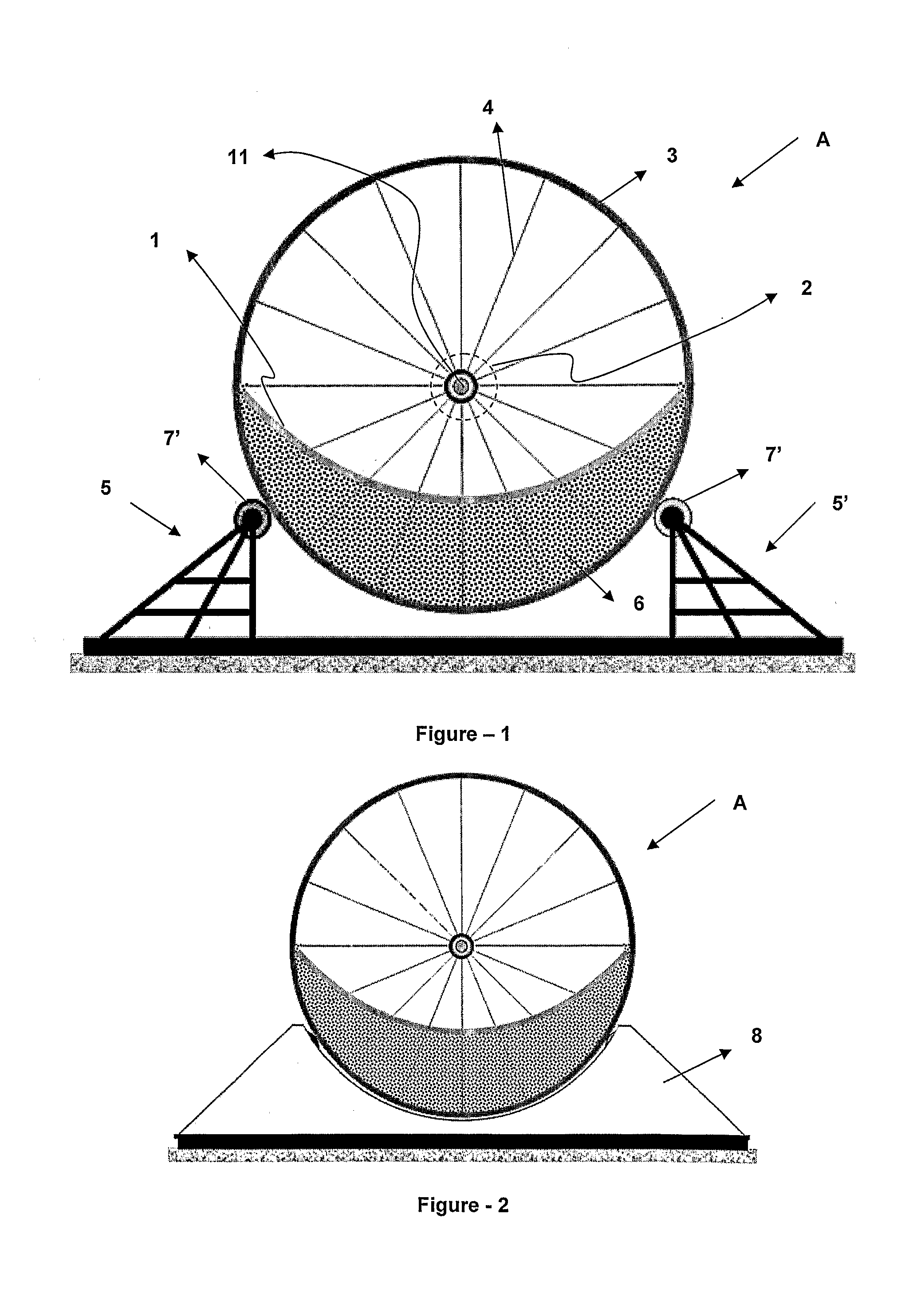
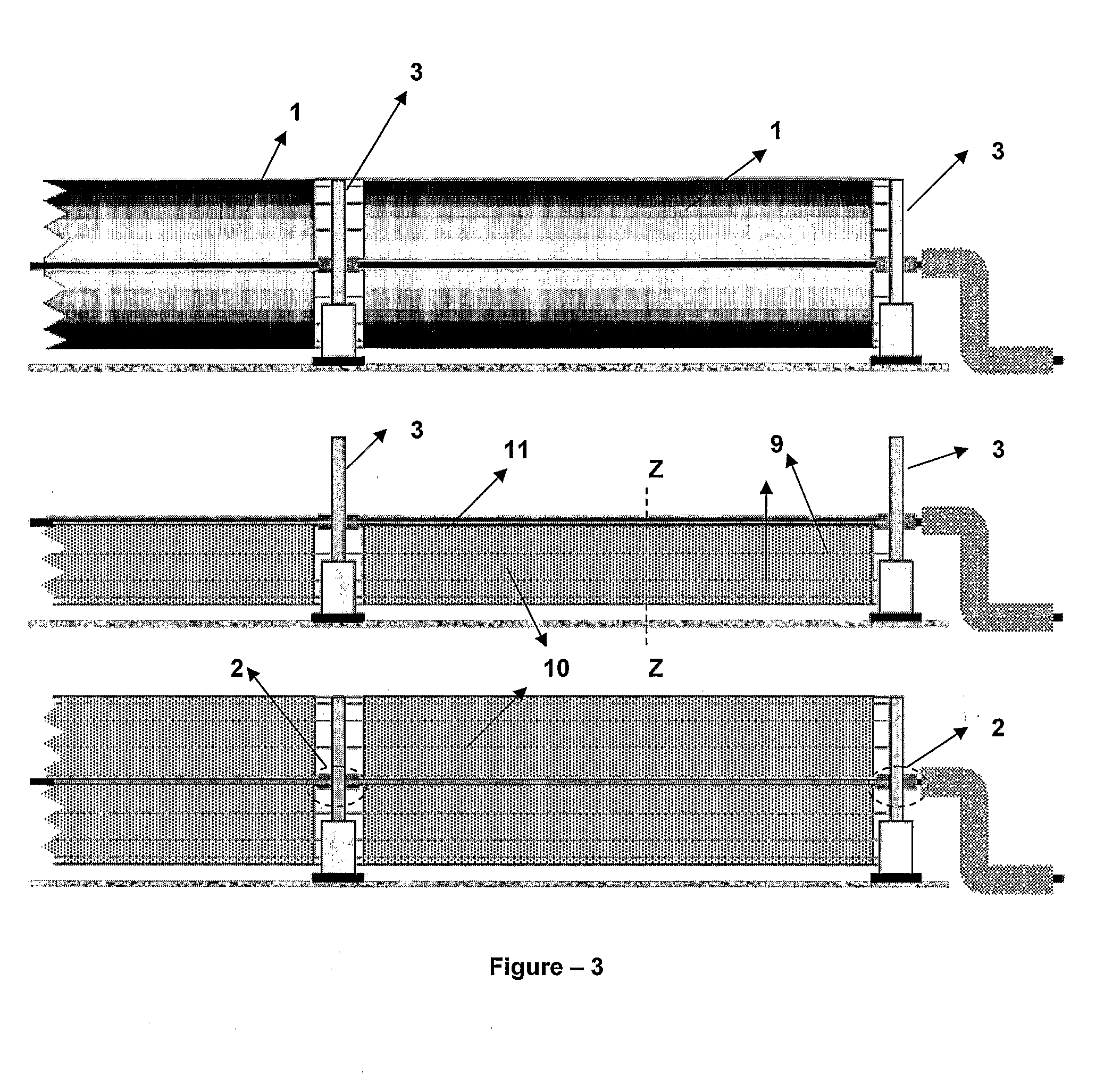
[0052]FIG. 1 provides a side view of the inventive solar trough field system (A). A solar trough field system (A) comprises multiple parabolic reflectors (1), support circles (3) of which the center coincides with the focus of the parabolic reflector (1) and which are used in order to support the reflector (1); core mechanisms (2) which are located on the center of the circles (3); guy wires (4) which connect the circle (3) and the core mechanism (2) to each other; side support units (5, 5′) which bear the support circles (3) from their outer surfaces; lightweight filling materials (6) which support the reflectors (1) from their lower parts; thermal receiver tubes (11) which pass through the center axis of the circles (3). The solar trough field system (A) is rotated around the center axis of the circles (3) and in this way; the parabolic reflectors (1) are also directed towards the sun by rotating in this rotation axis which is their focus. Thus, the parallel beams coming from the ...


PUM


Abstract

The inventive solar trough field system (A) comprises multiple parabolic reflectors (1), support circles (3) of which the center coincides with the focus of the parabolic reflector (1 ) and which are used in order to support the reflector (1), core mechanisms (2) which are located on the center of the circles (3), guy wires (4) which connect the circle (3) and the core mechanism (2) to each other, side support units (5,5J) which bear the support circles (3) from their outer surfaces, lightweight filling materials (6) which support the reflectors (1) from their lower parts, thermal receiver tubes (11) which pass through the center axis of the circles (3). The parabolic reflectors (1) are rotated around the center axis of the circles (3), which is the focus thereof, and directed towards the sun. Thus, the parallel beams coming from the sun are concentrated in the thermal receiver tubes (11) which are located in the focus of the reflectors (1).

Description

TECHNICAL FIELD[0001]This invention relates to the developments on parabolic trough-shaped collectors which concentrate the sunlight on a focus and convert it into another energy forms such as heat and electricity.PRIOR ART[0002]Currently, trough collectors (solar trough field system) are used to collect the sun's energy in order to obtain electricity and heat therefrom. These systems comprise trough-shaped long parabolic reflectors, thermal receiver tubes which are placed on the focus of the reflectors where beams coming from the reflector are collected and in which a fluid exists, and a rotating mechanism which directs the reflectors to the location where the sun is. The beams coming to the reflectors which are directed towards the sun are reflected and collected on the thermal receiver tube which is located on the focus of the reflector. Thermal receiver tube is provided with two nested tubes where a vacuum setting is located in the space therebetween. A fluid, which provides the...

Claims


Application Information

Patent Timeline
Patent Type & Authority Applications(United States)
IPC IPC(8): F24J2/46F24S23/74F24S23/79F24S50/20
CPCF24J2/07F24J2/14F24J2/18Y02E10/47Y02E10/41Y02E10/45F24J2/541F24S23/74F24S23/79F24S20/20F24S30/425Y02E10/40
Inventor CAPAN, RAHMI OGUZ
Owner HSE HITIT SOLAR ENERJI ANONIM SIRKETI
Why Eureka
Try Eureka