High-safety die forging ball valve

A safe, die-forging technology, applied in valve details, valve devices, shaft seals, etc., can solve problems such as adverse effects on service life and sealing performance, excessive valve opening and closing torque, and difficult maintenance and operation, achieving long service life, The valve opening and closing torque is small, and the effect of improving the sealing effect

Pending Publication Date: 2019-09-27
OVIKO GRP CO LTD
View PDF0 Cites 0 Cited by
  • Summary
  • Abstract
  • Description
  • Claims
  • Application Information

AI Technical Summary

Problems solved by technology

However, most of the existing ball valves are made of two-piece castings or forgings, and there are many leakage points, many casting defects, pores or trachoma, and the preload pressure of the valve seat is not easy to control; and the ball of the existing ball valve is under the action of the fluid medium. It will be pushed to the outlet side, which will generate a driving force on the bottom of the valve stem, which will easily cause the valve stem to bend and deform. The service life is short and frequent maintenance is required, but the maintenance operation is difficult, inconvenient to use, and poor in practicability

Method used


Image

  • High-safety die forging ball valve
  • High-safety die forging ball valve
  • High-safety die forging ball valve

Examples


Embodiment 1

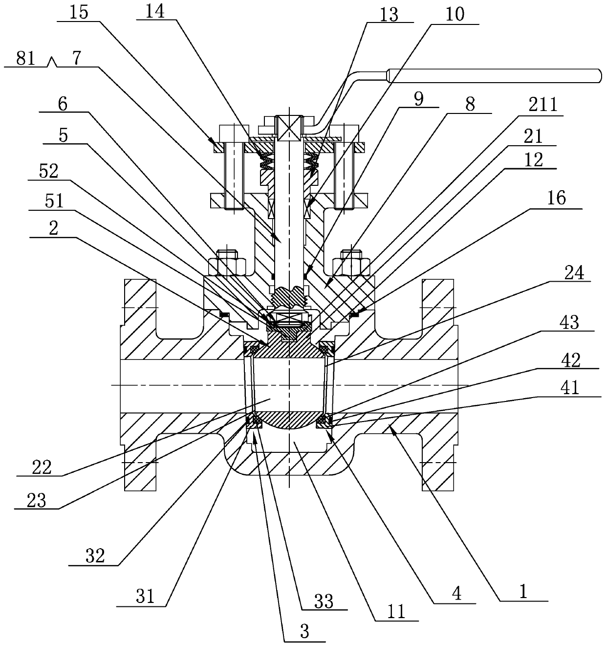
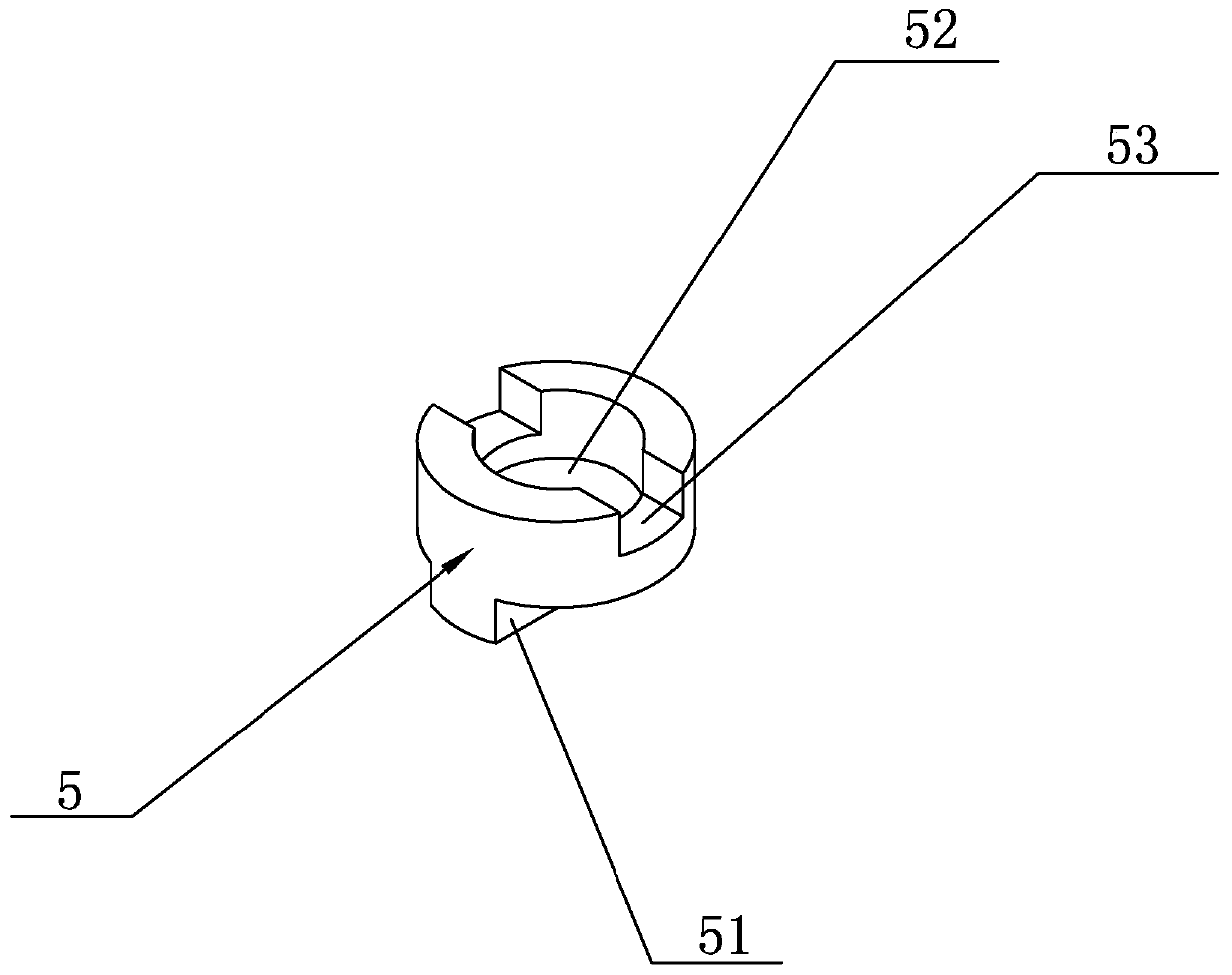
[0019] see figure 1 with figure 2 , a high-safety forged ball valve disclosed in the present invention, comprising a valve body 1, a valve chamber 11 is arranged inside the valve body 1, a valve ball loading port 12 is arranged at the upper end of the valve chamber 11, and a valve chamber 11 is provided inside the valve chamber 11. A valve ball 2 is provided, the left end of the valve ball 2 is provided with a first inclined-plane combined valve seat 3, the right end of the valve ball 2 is provided with a second inclined-plane combined valve seat 4, and the upper end of the valve ball 2 is provided with a positioning boss 21 A positioning groove 211 is vertically provided in the middle of the positioning boss 21, a slider 5 is arranged on the positioning boss 21, and a positioning protrusion 51 is integrally provided on the lower end surface of the slider 5, The positioning protrusion 51 is inserted into the positioning groove 211, and a spring groove 52 is vertically arrang...

Embodiment 2

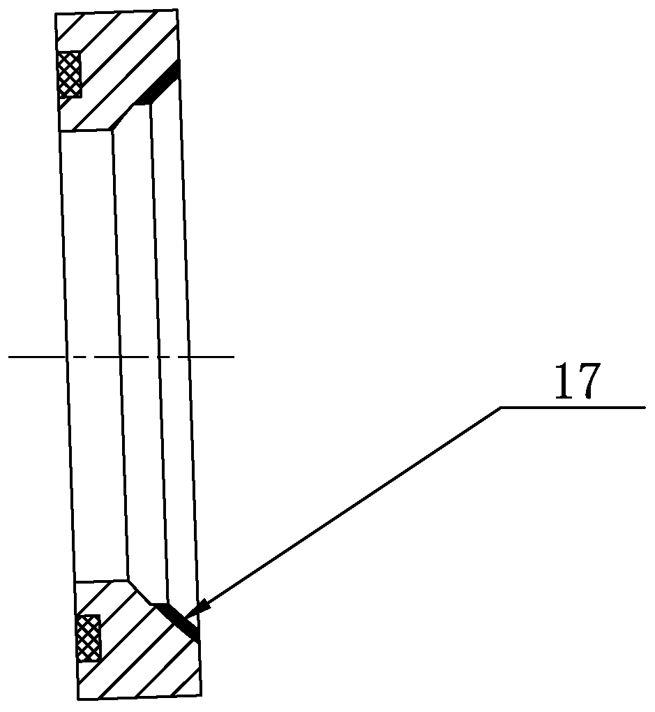
[0030] see image 3 , the second embodiment is to improve the valve seat on the basis of the first embodiment above: the valve ball sealing ring of the inclined-plane combined valve seat is replaced by a surfacing welding carbide layer 17 to make it a hard-sealed ball valve, that is, the above-mentioned A cemented carbide sealing layer 17 is welded on the right end surface of the first metal support ring 31 and the left end surface of the second metal support ring 41 .


PUM


Abstract

The invention discloses a high-safety die forging ball valve. The high-safety die forging ball valve comprises a valve body, wherein a valve ball loading port is formed in the upper end of a valve cavity of the valve body, a valve ball is arranged inside the valve cavity, a first inclined plane combined type valve base is arranged at the left end of the valve ball, and a second inclined plane combined valve base is arranged at the right end of the valve ball; a positioning boss is arranged at the upper end of the valve ball, a positioning groove is vertically formed in the middle of the positioning boss, a sliding block is arranged on the positioning boss, a positioning lug is integrally arranged on the lower end surface of the sliding block, and the positioning lug is inserted into the positioning groove; a spring groove is vertically formed in the middle of the upper end surface of the sliding block, a spring assembly is arranged inside the spring groove in a embedded mode, a valve rod is arranged right above the spring assembly, and a valve cover is arranged on the valve rod in a sleeved mode. According to the technical scheme, the structure design is reasonable, the structure is simple, the high-safety die forging ball valve is not easy to leakage, the sealing performance is good, the valve rod is not easy to bend or deform, the valve opening and closing torque is small, the maintenance is convenient, the service life is long, the work is stable, and the practicability is good.

Description

technical field [0001] The invention relates to the technical field of valves, in particular to a high-safety forging ball valve. Background technique [0002] Floating ball valve is a fluid control product with a large quantity and a wide range, which is widely used in various pipeline systems. However, most of the existing ball valves are made of two-piece castings or forgings, and there are many leakage points, many casting defects, pores or trachoma, and the preload pressure of the valve seat is not easy to control; and the ball of the existing ball valve is under the action of the fluid medium. It will be pushed to the outlet side, which will generate a driving force on the bottom of the valve stem, which will easily cause the valve stem to bend and deform. The service life is short and frequent maintenance is required, but the maintenance operation is difficult, inconvenient to use, and poor in practicability. Contents of the invention [0003] In view of the defic...

Claims


Application Information

Patent Timeline
Patent Type & Authority Applications(China)
IPC IPC(8): F16K5/06F16K5/20F16K5/08F16K41/02F16K41/06
CPCF16K5/0605F16K5/0689F16K5/0694F16K5/08F16K5/201
Inventor 邵力平陈忠信母泽冰陈芳芳徐林娟林时艳王业先邵佳慧邵磊江凯其他发明人请求不公开姓名
Owner OVIKO GRP CO LTD
Why Eureka
Try Eureka