Modular sump pump pit assembly

a sump pump and module technology, applied in the direction of pumping, positive displacement liquid engines, liquid fuel engines, etc., can solve the problems of limited height clearance in many crawl spaces, significant difficulty in adding a sump pump system to an existing building, etc., and achieve the effect of convenient portability and added durability

Inactive Publication Date: 2009-07-23
COLE LOUIS F +1
View PDF14 Cites 24 Cited by
  • Summary
  • Abstract
  • Description
  • Claims
  • Application Information

AI Technical Summary

Benefits of technology

[0010]The inventive sump pump pit utilizes a multiple component construction, comprised as two pairs of separate respectively similar side walls, and two generally similar top and bottom walls. These wall components can be shipped separate, compactly stacked f

Problems solved by technology

However, adding a sump pump system to an existing building has been significantly more difficult, such as where the sump hole might have to be dug in tight quarters of a crawl space.
Specifically, many crawl spaces have only limit

Method used


Image

  • Modular sump pump pit assembly
  • Modular sump pump pit assembly
  • Modular sump pump pit assembly

Examples


Embodiment Construction

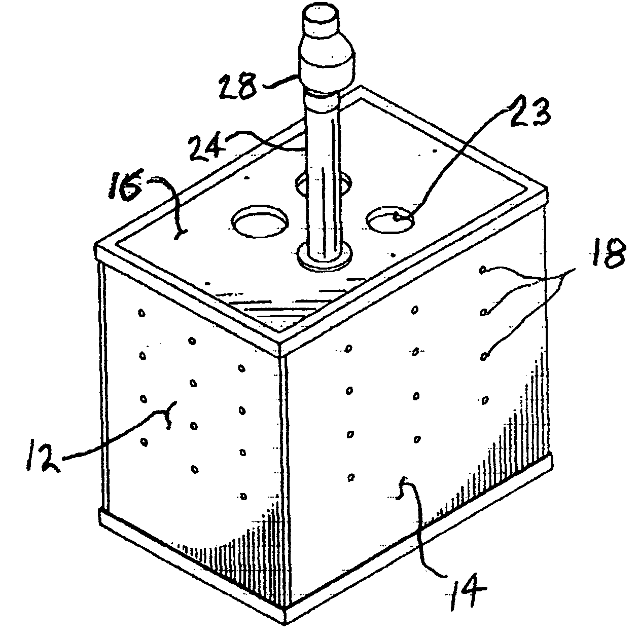
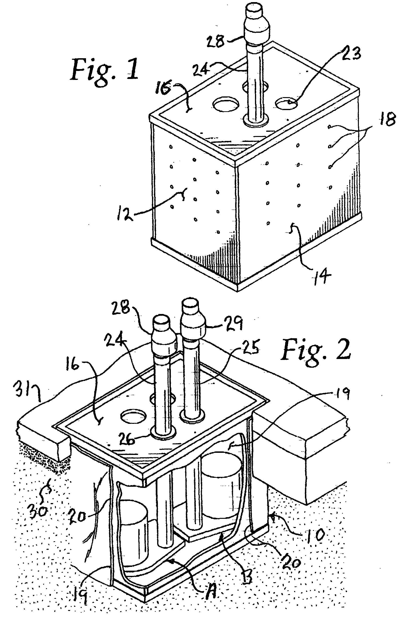
[0017]The invention provides an improved sump pump pit 10 of generally rectangular cross section, suited to hold side-by-side two sump pumps, such as but not limited to the combination of a conventional AC electric utility powered pump “A” and a DC storage battery powered backup pump “B”.

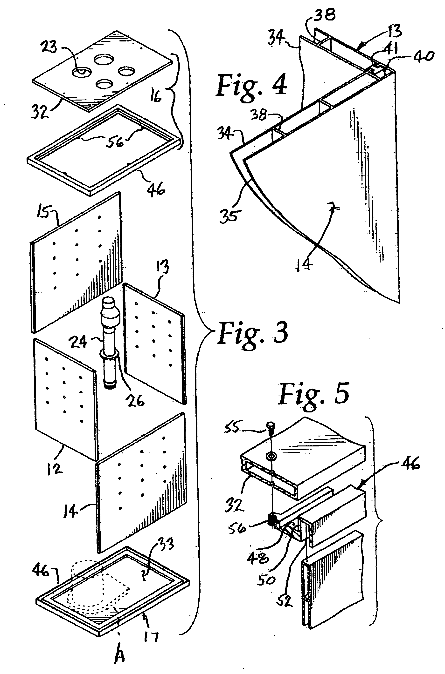
[0018]The inventive sump pump pit 10 utilizes a multiple component construction, comprised of two pairs 12, 13 and 14, 15 of similar rectangular side walls, and two generally similar rectangular top and bottom walls 16, 17, to define a pit enclosure 19. The pit side walls 12, 13, 14 and 15 can have many small openings 18 therein suited to allow water to pass inwardly to the pit enclosure 19. A porous fiber mesh wrap 20, such as of a geotextile material, can if desired overlie the side walls to filter stones or like solid debris from passing into the pit enclosure, which could damage the pump if pumped through it.

[0019]The two independent pumps “A” and “B” can be housed in the sump pit enclosure 19, ...


PUM


Abstract

The disclosed sump pump pit is modular, being formed from substantial planar lightweight top, bottom and side walls that when disassembled can be carried compactly stacked on one another to an intended sump hole, and can then be assembled and secured together as the rigid pit defining an enclosure sized to hold at least one sump pump (preferably two sump pumps side-by-side). Cooperating tongue and groove configurations on the side wall edges interlock these components in a tubular configuration, and the end edges of the side walls can be fitted into and secured in channels in the top and bottom walls, making the pit rigid. The pit walls are perforated for communicating the sump hole with the pit enclosure. Piping extended through the top wall allows water to be pumped from the sump hole via the pit pump(s).

Description

RELATED APPLICATION[0001]This application is related to a Provisional Application from the same inventors, filed on Feb. 22, 2008 and possibly having App. No. 61 / 011,831 (filing receipt No. 6756 received by attorney having this number, except identifying a different invention which corresponds to a second Patent Application concurrently filed by the same attorney, in fact in the same envelope. This attorney to date has received no filing receipt for this second Application invention, although the USPTO has collected the $105 and $515 filing fees for these Applications.BACKGROUND OF THE INVENTION[0002]Buildings typically have a perimeter footing buried in the ground below the frost line, with an upstanding perimeter foundation supported thereon to rise above the ground. Building side walls are supported on the foundation (or footing) above the ground level. A building floor (basement, crawl space or first floor) typically is defined inside of the foundation perimeter, frequently comp...

Claims


Application Information

Patent Timeline
IPC IPC(8): F04B53/16
CPCE03F5/22F04D13/08F04D13/068F04D29/628F04D13/16Y10T137/6991
Inventor COLE, LOUIS F.CHIRICHIELLO, DOUGLAS
Owner COLE LOUIS F
Why Eureka
Try Eureka