
Temperature-resistant electrical line

Inactive Publication Date: 2009-07-23
ZIEMEK CABLE TECH
View PDF1 Cites 3 Cited by
  • Summary
  • Abstract
  • Description
  • Claims
  • Application Information

AI Technical Summary

Benefits of technology

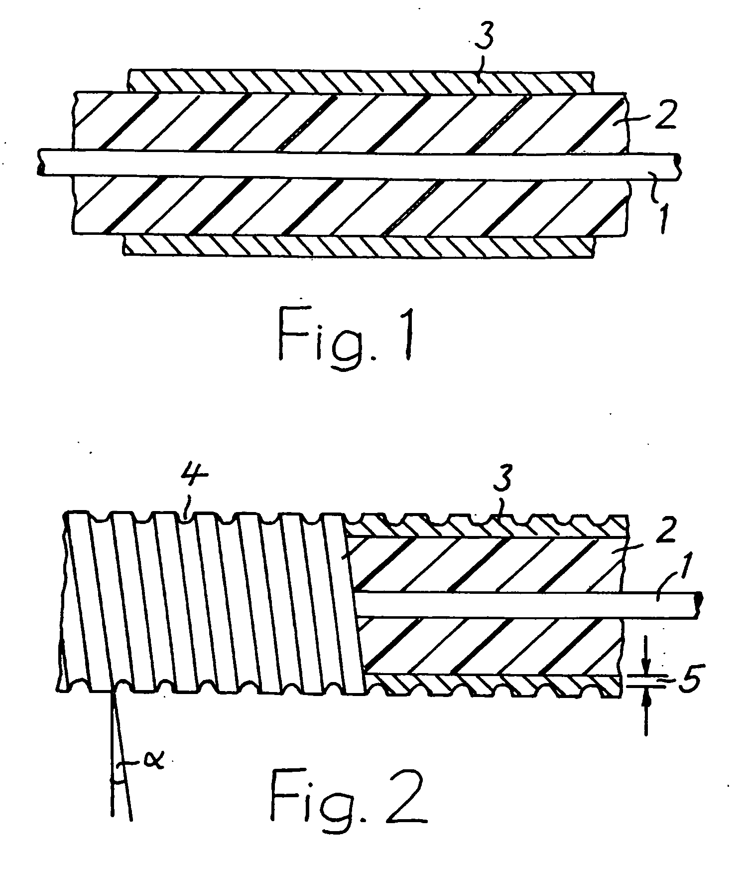
[0005]This object is achieved according to the invention by virtue of the fact that the outer tube has, over its entire length, a notch, which is open on the outside, runs in a helical fashion, is produced once the line is finished by means of a metal-removing tool and whose depth is at least 50% of the wall thickness of the outer tube, with a residual wall thickness which ensures the stability thereof.
[0006]The overall bending resistance of the line is determined in terms of dimensions by its outer tube, referred to below as “tube” for short, with its large wall thickness. The flexibility of the tube in the case of this line is substantially increased by the notch produced in it once it is finished, so that the entire line also becomes elastically so flexible that it can be stranded, for example, together with other stranding elements, using conventional stranding machines. The line can also be manufactured with a greater length and be wound onto a spool and be unwound from the spool again for laying purposes. The tube, despite the notch, maintains its high transverse stability, with the result that the line is not damaged by radial loads and in particular the mineral insulation is effectively protected. As a result of the notch, the outer surface of the tube is also enlarged, so that, as an additional advantage of this line during use thereof for heating purposes, the heat transfer to its surrounding environment is improved as a result of the enlarged transfer area for the heat produced by the conductor, which is then in the form of a heating conductor.

Problems solved by technology

Since these lines do not burn as a result of their mineral insulation, they are also used in sectors with increased risk of fire.
It can therefore not be further-processed using conventional methods and machines in cable technology and cannot be transported using conventional transport means, in particular spools.

Method used


Image

  • Temperature-resistant electrical line
  • Temperature-resistant electrical line

Examples


Embodiment Construction

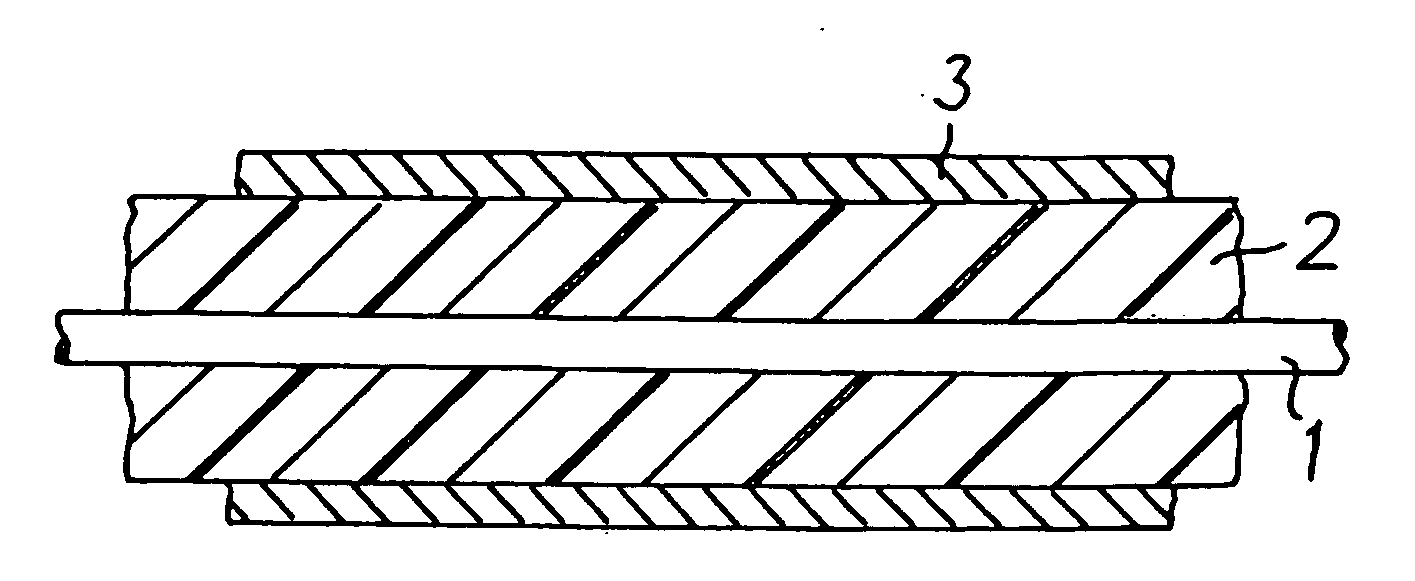
[0010]The line illustrated schematically in FIG. 1 as a section is known per se. It has a central electrical conductor 1, which is surrounded by insulation 2 made from a mineral material. In a preferred embodiment, the conductor 1 is a heating conductor. As a deviation from the illustration in the drawing, two or more conductors may also be provided. A metallic tube 3, which is preferably made from steel and bears against the insulation 2, is fitted over said insulation 2. The line has been produced corresponding to the method described at the outset. It therefore already has the reduced dimensions in comparison with the initial form. These dimensions are, for example, 17.5 mm for the outer diameter of the insulation 2 and 1.5 mm for the wall thickness of the tube 3. As a result of this thick tube 3, the line, which without the tube is flexible per se, is so rigid that, as has already been mentioned further above, it cannot be further-processed using methods and machines conventiona...


PUM

PropertyMeasurementUnit
Fractionaaaaaaaaaa
Angleaaaaaaaaaa
Angleaaaaaaaaaa

Abstract

A temperature-resistant electrical line comprises at least one central electrical conductor, an insulation, which is made from a mineral material and surrounds the electrical conductor completely, and a metallic outer tube, which bears against the insulation. The outer tube (3) has, over its entire length, a helical notch (4), which is open to the outside, and which is produced once the line is finished by means of a metal-removing tool and whose depth is at least 50% of the wall thickness of the outer tube (3), with a residual wall thickness (5) which ensures the stability thereof.

Description

CROSS REFERENCE TO RELATED APPLICATION[0001]This application claims priority under 35 USC §119 to German Patent Application No. DE 102008004781.3 which was filed on Jan. 17, 2008.TECHNICAL FIELD[0002]The invention relates to a temperature-resistant electrical line, comprising at least one central electrical conductor, insulation, which is made from a mineral material and surrounds the electrical conductor all the way around, and a metallic outer tube, which bears against the insulation.BACKGROUND OF THE INVENTION[0003]Such lines are known and have been available on the market for years. They are used, for example, as heating lines when very high temperatures in the region of 500° C. and more are intended to be produced. Since these lines do not burn as a result of their mineral insulation, they are also used in sectors with increased risk of fire. In order to produce them, first at least one electrical conductor is arranged centrally in a metallic, primarily steel or copper outer tu...

Claims


Application Information

Patent Timeline
IPC IPC(8): H01B9/02B23P19/00
CPCY10T29/532H05B3/48
Inventor ZIEMEK, GERHARD
Owner ZIEMEK CABLE TECH
Learn More