
Device and method for altering the characteristics of three-dimensional shaped parts using electrons and use of said method

Inactive Publication Date: 2009-07-23
FRAUNHOFER GESELLSCHAFT ZUR FOERDERUNG DER ANGEWANDTEN FORSCHUNG EV
View PDF51 Cites 18 Cited by
  • Summary
  • Abstract
  • Description
  • Claims
  • Application Information

AI Technical Summary

Benefits of technology

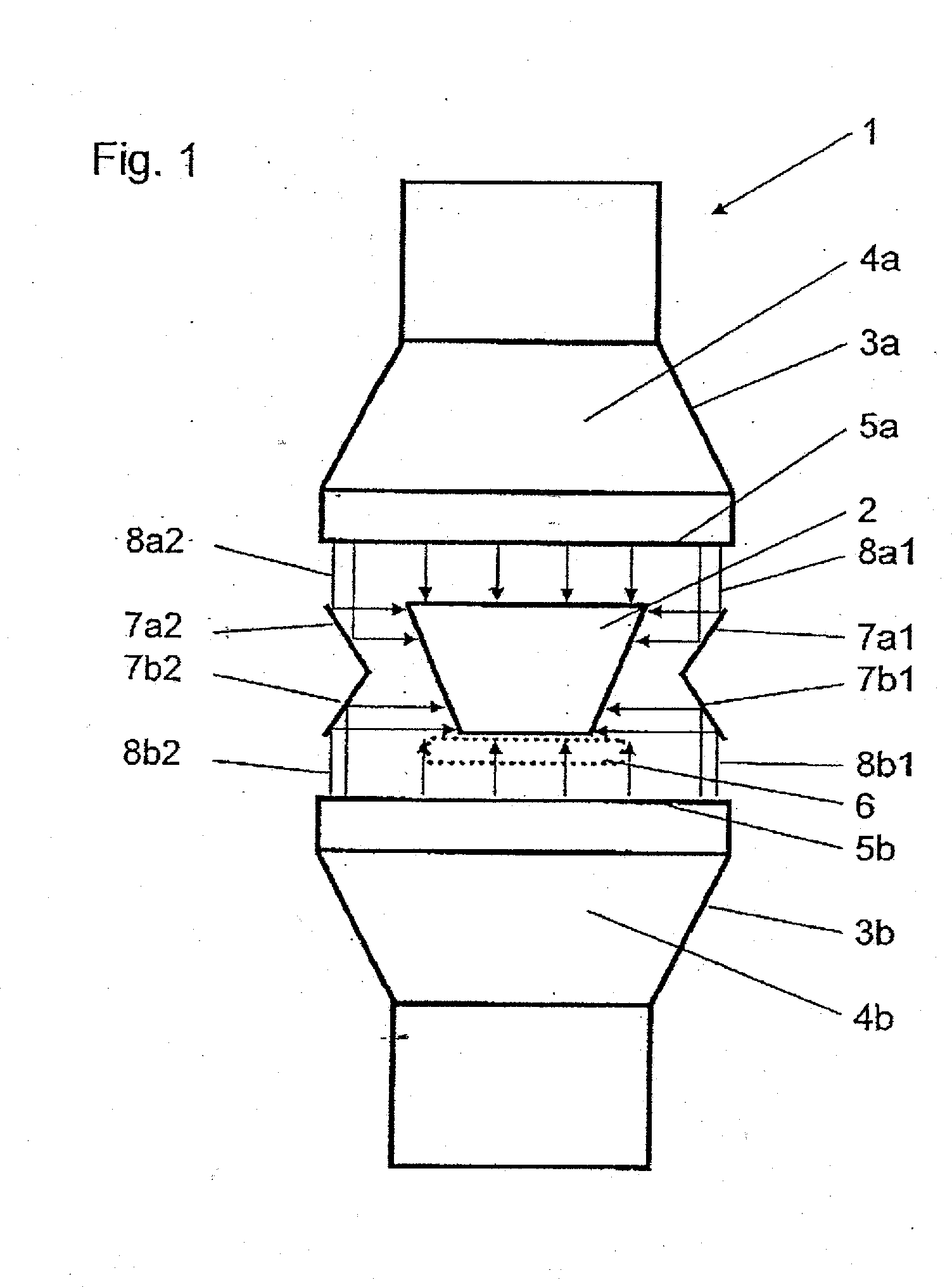
[0024]According to the prior art, it was hitherto assumed that at least two electron exit windows with lateral displacement or with an absorber located between them or with limited beam current or three electron exit windows are necessary in order to be able to bombard the cross-sectional circumference of a three-dimensional molded part in one pass completely with electrons and to produce the desired changes in characteristics. It is shown according to the invention that a limitation of the beam current resulting from an arrangement of electron exit windows opposite one another is not necessary and in addition a bombardment of a molded part surface with a virtually uniformly distributed energy dose is possible.
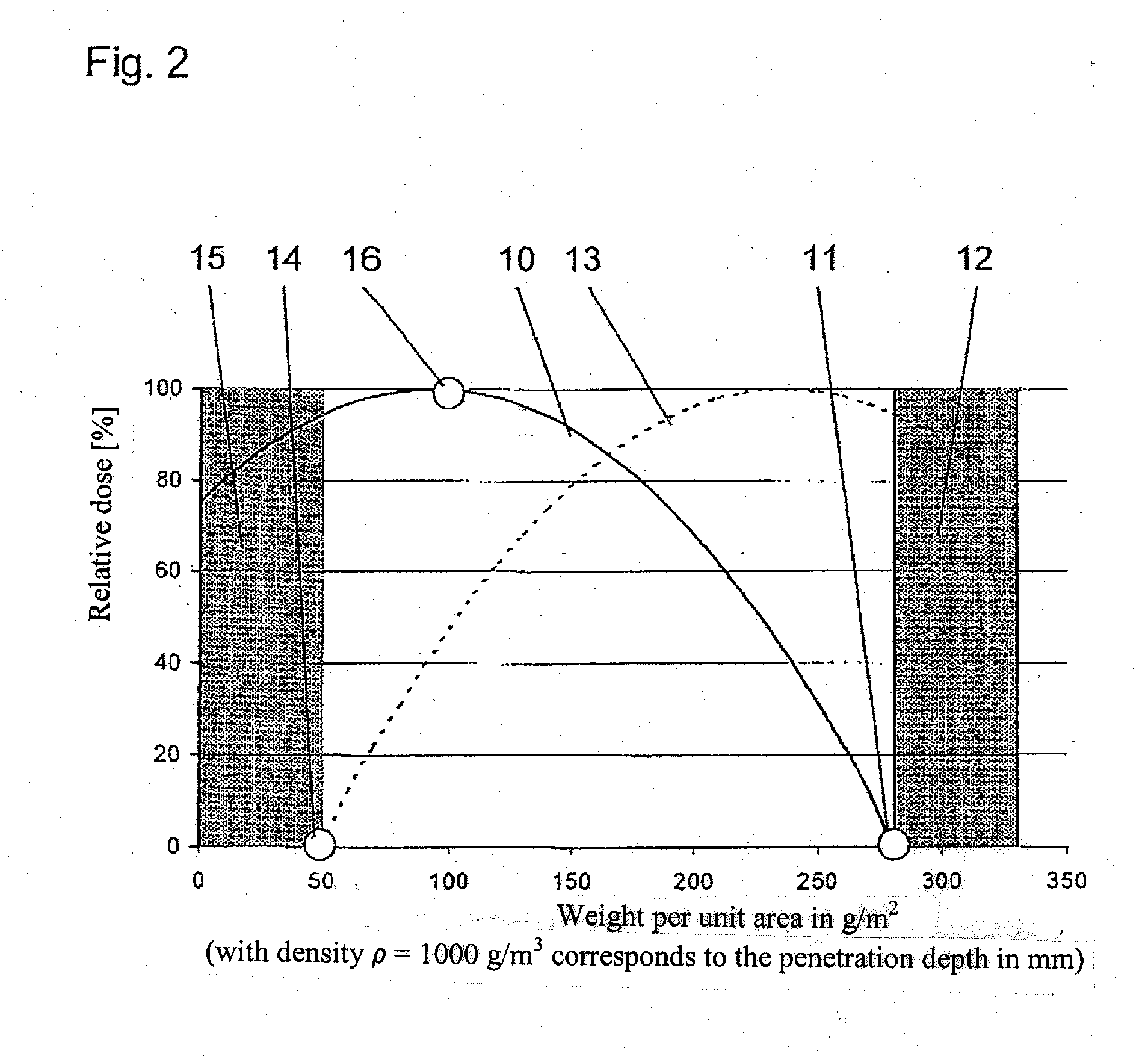
[0030]With a parallel alignment of two opposite electron exit windows embodied in a flat manner with optimum spacing and arrangement according to the invention of a reflector system, it was possible to realize overdose factors below the value 4 during the electron treatment of molded parts with largely trapezoidal cross section, whereas with the treatment of identical molded parts in devices according to the prior art with three electron exit windows or with two electron exit windows lying opposite one another and an absorber lying between them, overdose factors of far more than 4 had to be accepted. Compared with known solutions, thus with high productivity on the one hand energy is saved and on the other hand the surface of the three-dimensional product is protected from radiation-chemical damage and side effects damaging to the process are reduced due to the lower discharge of ozone.
[0033]It is particularly advantageous if the energy density distributions are detected and correspondingly evaluated in this manner in the x, y and z direction of a Cartesian coordinate system.
[0036]In addition to flat shaped electron exit windows, these can also be embodied, for example, in a concave manner towards the molded part or also adapted to the geometry of the molded part, which likewise causes as many surface sections of the molded part as possible to be spaced apart by virtually the same measurement from the respective energy-emitting electron exit window, whereby lower overdose factors can be achieved.
[0042]A method according to the invention for altering characteristics of a three-dimensional molded part by means of electrons is characterized in that electrons are generated, accelerated and emitted over the surface of two electron exit windows lying opposite one another by means of at least one electron accelerator, wherein the two electron exit windows and at least one electron reflector delimit a process chamber in which the surface or an edge layer of the molded part is bombarded with electrons, wherein an energy density distribution within the process chamber is detected over at least one spatial dimension by means of a sensor system and the spacing of the electron exit windows is adjusted such that an influence of an electron exit window by the emitted energy of the electron exit window lying opposite is negligible.

Problems solved by technology

The disadvantage that all surface areas (in particular the areas that run largely perpendicular to the surface of the electron exit windows) of the molded part to be modified are no longer bombarded sufficiently with electrons with a distance of this type, is offset in that the reflector is shaped and arranged such that electrons (in particular from the edge areas of the electron exit windows) which would not strike the molded part, are reflected by the reflector onto the surface areas of the molded part that exhibit a deficit in the bombardment with electrons.

Method used


Image

  • Device and method for altering the characteristics of three-dimensional shaped parts using electrons and use of said method
  • Device and method for altering the characteristics of three-dimensional shaped parts using electrons and use of said method
  • Device and method for altering the characteristics of three-dimensional shaped parts using electrons and use of said method

Examples


Embodiment Construction

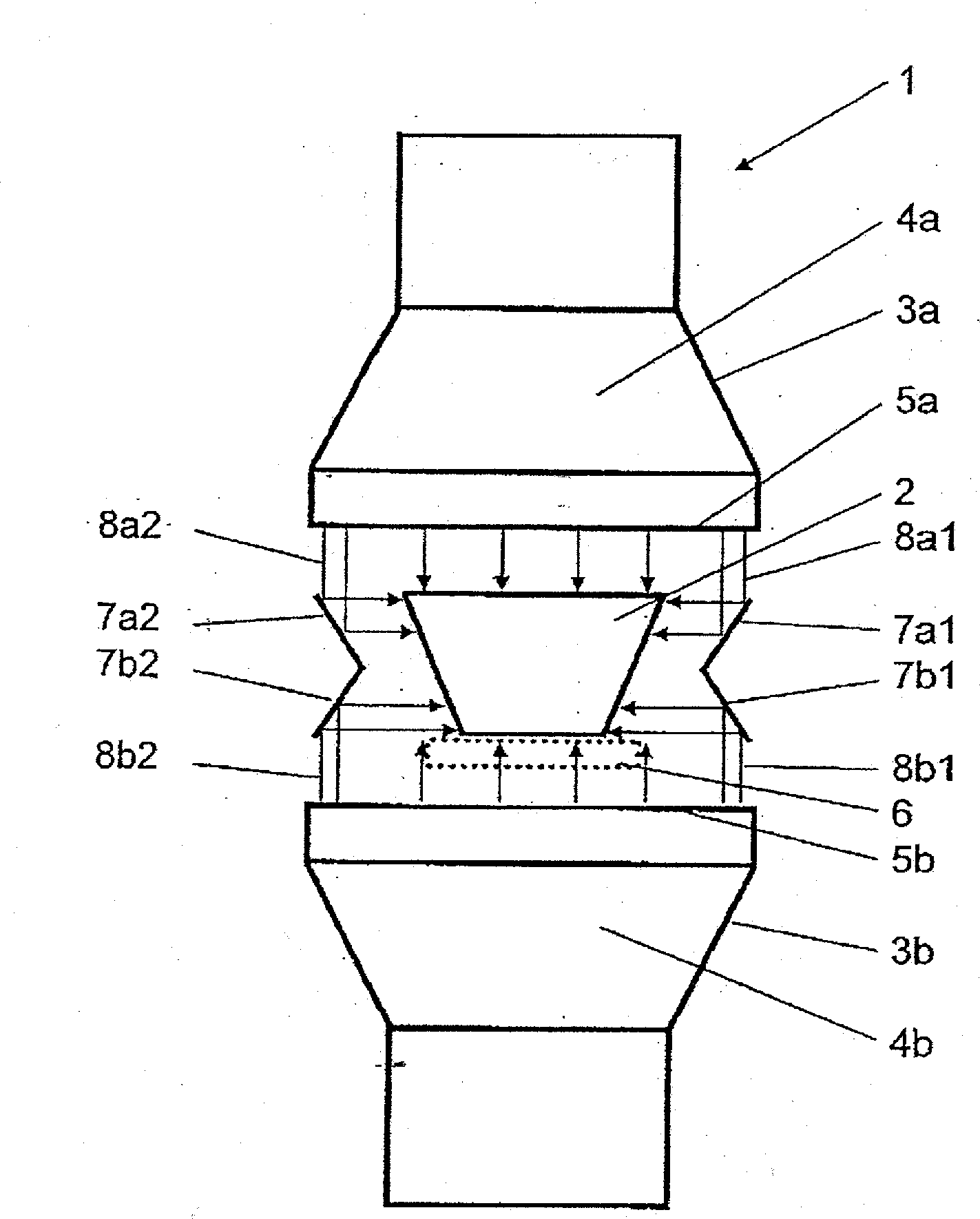
[0065]In FIG. 1 a device 1 for electron treatment for the purpose of sterilizing the surface of a molded part 2 is shown diagrammatically in cross section. Molded part 2 is an elongated object with a trapezoidal cross section. Device 1 comprises two electron accelerators 3a, 3b embodied as shaped beam generators 3a, 3b that respectively comprise an electron acceleration chamber 4a, 4b and an electron exit window 5a, 5b. The electron exit windows are hereby embodied as a titanium film 11 μm thick. The electron accelerators 3a, 3b are arranged such that the flat shaped electron exit windows 5a, 5b are aligned parallel opposite one another. Molded part 2 is guided continuously through between the two electron exit windows 5a, 5b on a conveyor belt system 6 interrupted in the area of the electron exit window 5b and shown by a dotted line in FIG. 1 and the entire surface thereof is thereby bombarded with electron energy. Respectively, the lowest energy dose is thereby transferred to the ...


PUM

PropertyMeasurementUnit
temperatureaaaaaaaaaa
thickaaaaaaaaaa
thickaaaaaaaaaa

Abstract

The invention relates to a device and a method for altering the characteristics of a three-dimensional molded part by means of electrons, including at least one electron accelerator for generating accelerated electrons and two electron exit windows, wherein the two electron exit windows are arranged opposite one another, wherein the two electron exit windows and at least one reflector delimit a process chamber in which the surface or an edge layer of the molded part are bombarded with electrons, wherein an energy density distribution inside the process chamber can be detected at least over one spatial dimension by means of a sensor system.

Description

CROSS-REFERENCE TO RELATED APPLICATIONS[0001]This application is a national phase of international application PCT / EP2007 / 002458, which international application was filed on Apr. 4, 2007.[0002]In addition, this application claims priority under 35 U.S.C. § 119 of German Patent Application No. 10 2006 012 668.8-54, filed on Mar. 20, 2006.BACKGROUND OF THE INVENTION[0003]1. Field of the Invention[0004]The invention relates to a device and a method for modifying material characteristics on the surface and in the edge area of three-dimensional molded parts using the energy of electrons. Furthermore, uses of the method are shown.[0005]2. Background Information[0006]Using electrons, energy can be fed into materials in a spatially and chronologically determinate manner in order to alter their material characteristics on the surface, in the edge layer or in the volume. The electrons required to this end are generated, formed and accelerated in electron accelerators before they are guided v...

Claims


Application Information

Patent Timeline
Patent Type & Authority Applications(United States)
IPC IPC(8): A61N5/00
CPCA61L2/087A61L2202/14H01J33/00A61L2202/24A61L2202/23
Inventor BARTEL, RAINERKIRCHHOFF, VOLKERMATTAUSCH, GOESTAROEDER, OLAFKUBUSCH, JOERG
Owner FRAUNHOFER GESELLSCHAFT ZUR FOERDERUNG DER ANGEWANDTEN FORSCHUNG EV
Learn More