Electromagnetic Load Controller

a load controller and electromagnet technology, applied in the direction of electric control, magnetic bodies, electric devices, etc., can solve the problems of requiring a large amount of energy for valve opening operation, circuit may misdiagnose that a short-circuit battery has occurred, and improvement in controllability may fail, so as to ensure the reliability and precision of fault diagnosis and improve safety.

Active Publication Date: 2009-07-23
HITACHI ASTEMO LTD
View PDF8 Cites 8 Cited by
  • Summary
  • Abstract
  • Description
  • Claims
  • Application Information

AI Technical Summary

Benefits of technology

[0010]The present invention has a feature that a current source or a voltage source is provided for controlling a potential of the diagnosis position in order to ensure a high-precision fault diagnosis even if the drive cycle of the electromagnetic load, such as the fuel injector, in the internal combustion engine is shortened. The present invention also has a feature that diagnosis timing is optimally set or the number of determinations for averaging is increased in order to ensure the high-precision fault diagnosis without being influenced by unexpected disturbance such as noises.
[0014]The internal combustion engine controller that drives the electromagnetic load can ensure the reliability and precision of the fault diagnosis of the electromagnetic load even when the drive cycle of the internal combustion engine becomes shorter. In addition, the high-precision fault diagnosis can be ensured without being influenced by the noises. Further, more improvement in safety can be expected because of the reliable fault diagnosis of the circuit that regenerates the counter electromotive energy into the booster circuit.

Problems solved by technology

Such a direct fuel injector uses high-pressure fuel and therefore requires a large amount of energy for valve opening operation.
However, in a case of short drive cycle (that is, when the rotating speed of the internal combustion engine increases), the conventional internal combustion engine controllers cannot set a fault-detection timing control properly, and a diagnosis circuit may misdiagnose that short-circuit to a battery has occurred, for example, although the drive circuit and the electromagnetic load are normal.
Moreover, an improvement in controllability may fail because it takes long time to return the potential of a diagnosis position to an initial state.
In addition, the diagnosis circuit may misdiagnose due to unexpected disturbance such as noises.
Besides, if the regeneration element breaks down by overload energy, the energy cannot be regenerated, resulting in a possible serious accident, such as heat generation or ignition of the device.

Method used


Image

  • Electromagnetic Load Controller
  • Electromagnetic Load Controller
  • Electromagnetic Load Controller

Examples


first embodiment

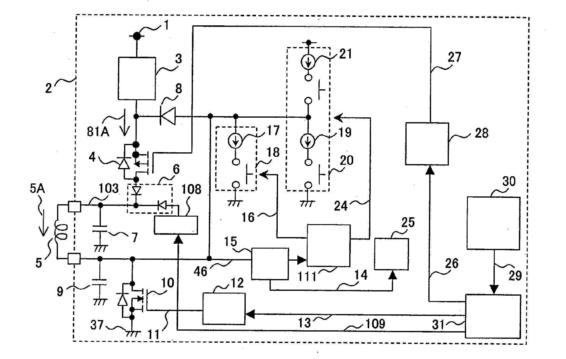
[0035]An internal combustion engine controller in accordance with a first embodiment of the present invention will be described with reference to FIGS. 1 and 3.

[0036]FIG. 1 shows a circuit configuration of an internal combustion engine controller 2 which includes a battery voltage 1, a booster circuit 3 that boosts the battery voltage 1, and an electromagnetic load 5 that is located between the booster circuit 3 and a ground 37.

[0037]The internal combustion engine controller 2 also includes a high-side driver 4 between the battery voltage 1 and the electromagnetic load 5, and a low-side driver 10 between the ground 37 and the electromagnetic load 5. The high-side driver 4 and the low-side driver 10 are drivers for the electromagnetic load 5, and comprise switching elements (for example, FETs) As used herein, “high side (upper or upstream side)” and “low side (lower or downstream side)” means, respectively, the battery voltage 1 side and the ground 37 side in relation to the electrom...

second embodiment

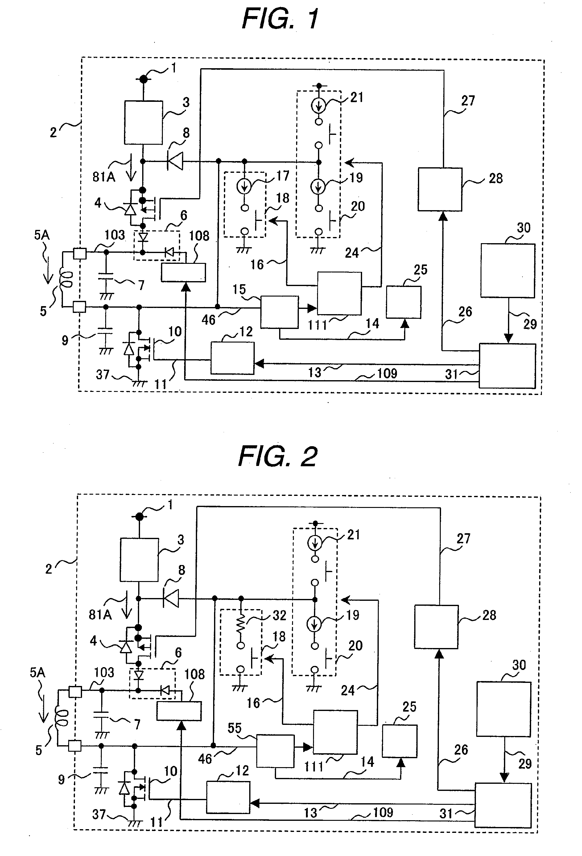
[0061]With reference to FIG. 2, a description will be given of an internal combustion engine controller in accordance with a second embodiment of the present invention.

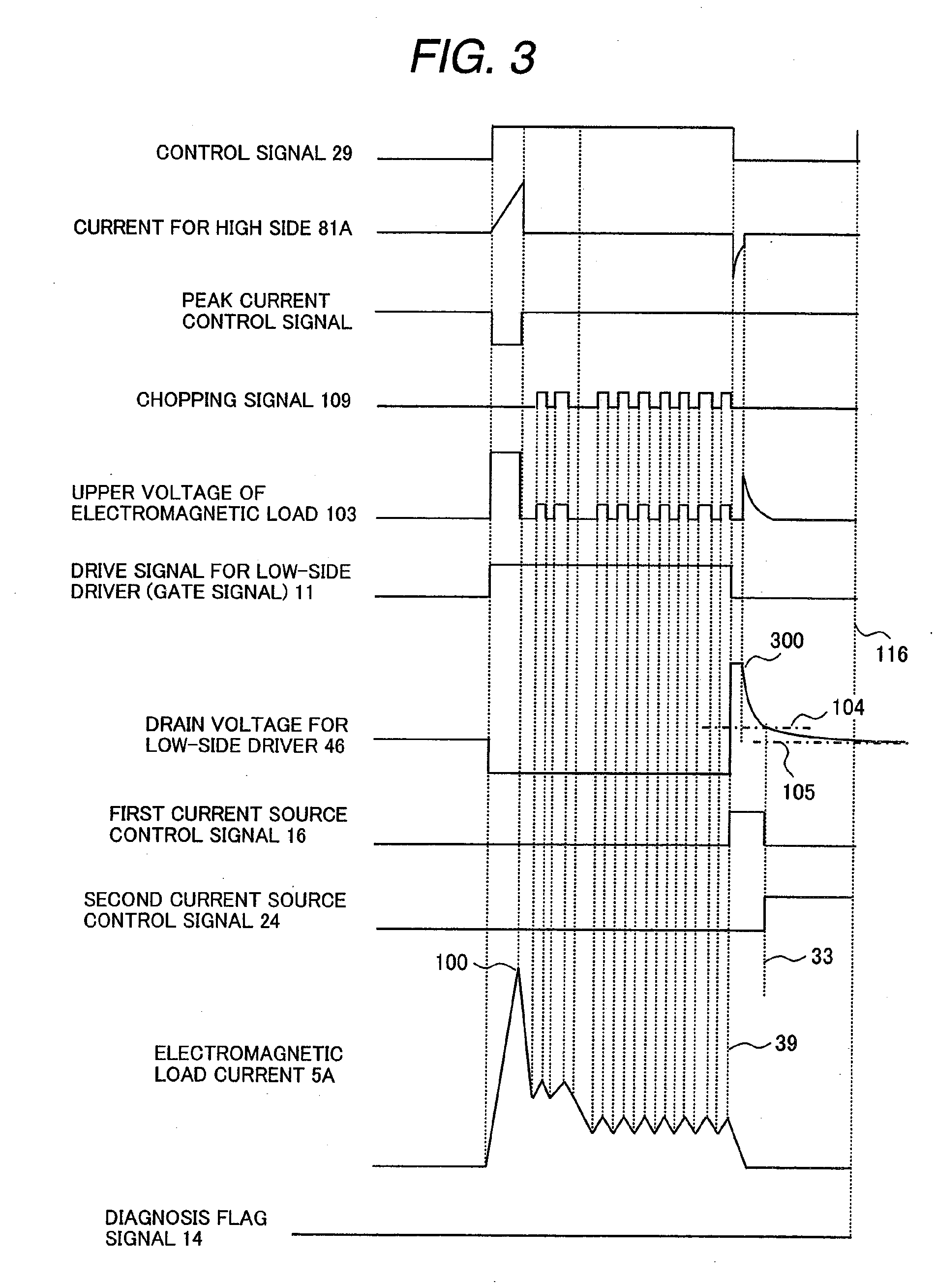
[0062]In the configuration of this embodiment, the first current source 17 shown in FIG. 1 is replaced with a first resistor for current source 32. The first resistor for current source 32 functions as a sink current resistor. The drain voltage for low-side driver 46, which has been charged in the lower capacitor of electromagnetic load for noise or surge 9, is consumed and discharged by the first resistor for current source 32. Therefore, the drain voltage for low-side driver 46 can rapidly attenuate as in the timing charts of the first embodiment shown in FIG. 3. Accordingly, the same advantages as in the first embodiment can be obtained in this configuration.

third embodiment

[0063]With reference to FIGS. 4 and 5, a description will be given of an internal combustion engine controller in accordance with a third embodiment of the present invention.

[0064]In the configuration of this embodiment, the positions of the diagnosis circuit 25 and its peripheral circuits in the first embodiment (FIG. 1) are changed from the downstream side of the electromagnetic load 5 to the upstream side thereof as shown in FIG. 4. The peripheral circuits include the first current source controller 18, the second current source controller 20, the voltage detector 15, and the drive signal selector for current control 111. In the first embodiment, the fault diagnosis of the electromagnetic load 5 is performed by detecting the drain voltage for low-side driver 46. In this embodiment, the fault diagnosis of the electromagnetic load 5 is performed by means of detection of a drain voltage for high-side driver 114 by the voltage detector 15 and a diagnosis by the diagnosis circuit 25.

[...


PUM


Abstract

An internal combustion engine controller that drives an electromagnetic load is provided for improving a fault diagnosis precision of the electromagnetic load and stabilizing a high-speed control without influence of noises even if the drive cycle of the electromagnetic load is short. The internal combustion engine controller has high reliability in a fault diagnosis for a circuit to regenerate counter electromotive energy. The internal combustion engine controller comprises a current source or a voltage source for controlling a potential of the diagnosis position in order to ensure a high-precision fault diagnosis even if the drive cycle of the electromagnetic load, such as the fuel injector, in the internal combustion engine is shortened. Diagnosis timing is optimally set or the number of determinations for averaging is increased in order to ensure the high-precision fault diagnosis without being influenced by unexpected disturbance such as noises. In the fault diagnosis of the regeneration circuit into the booster circuit, an input / output voltage or the regeneration current of a driving switching element of the electromagnetic load is detected.

Description

CLAIM OF PRIORITY[0001]The present application claims priority from Japanese Patent Application JP 2008-011584 filed on Jan. 22, 2008, the content of which is hereby incorporated by reference into this application.FIELD OF THE INVENTION[0002]The present invention relates to internal combustion engine controllers for automobiles, motorcycles, farm vehicles, industrial machines, or ships which use gasoline or light oil as fuel. More particularly, the present invention relates to electromagnetic load controllers, such as fuel injectors, which are driven by a battery voltage or a boosted battery voltage, and driving and fault diagnosis of the controllers.BACKGROUND OF THE INVENTION[0003]The internal combustion engine controllers for automobiles, motorcycles, farm vehicles, industrial machines, or ships which use gasoline or light oil as fuel are equipped with an injector (fuel injector) that injects fuel directly into cylinders to improve fuel consumption and engine output. Such a direc...

Claims


Application Information

Patent Timeline
Patent Type & Authority Applications(United States)
IPC IPC(8): B60L1/00
CPCH01F7/1844F02D41/20
Inventor OURA, RYOICHIWATANABE, MITSUHIKOMAYUZUMI, TAKUYAOKAMOTO, KANEYUKI
Owner HITACHI ASTEMO LTD
Why Eureka
Try Eureka